Wprowadzenie
W artykule przedstawiono najważniejsze decyzje pro-
jektowe podjęte przez prof. Wacława Zalewskiego (W.Z.),
które wpłynęły bezpośrednio na niezwykłą i niepowtó-
rzo ną dotąd na świecie formę hali widowiskowo-spor-
towej. Choć nie wszystkie rozwiązania proponowane
w pro jekcie konkursowym zostały zrealizowane, artykuł
poz woli prześledzić tok rozumowania [7], jaki dopro-
wadził Pro fesora do przełomowego odkrycia protoplasty
opatento wanego później nowego systemu konstrukcyj-
nego nazwanego tensegrity
1
.
Profesor Wacław Zalewski
– fazy pracy i realizacje
Profesor Wacław Zalewski jest polskim inżynierem bu-
downictwa i specjalistą w dziedzinie „filozofii kształ to-
wania konstrukcji”. Urodził się w 1917 r. w Sa mo gród ku,
do lat 60. XX w. pracował w Polsce, następnie w latach
1962–1966 w Wenezueli, a ostatecznie osiadł w USA, gdzie
do 1988 r. był zatrudniony na Wydziale Architektury MIT.
Kształtując konstrukcję, stosował me todę strumieni sił
nazwaną później Strut & Tie Method.
Wśród ważniej-
* Wydział Architektury Politechniki Wrocławskiej / Faculty of
Ar chitecture, Wrocław University of Technology.
1
System tensegrity to system prętowo-cięgnowy zbudowany
w taki sposób, że elementy sztywne nie stykają się ze sobą bezpośrednio.
Introduction
The article presents the most important decisions taken
by Prof. Wacław Zalewski (W.Z.), which have had a direct
impact on the unusual and hitherto unique form of the
discussed sports and entertainment hall. Although not all
of the solutions proposed in the contest design have been
implemented, the article will make it possible to follow
the process of reasoning [7] which has led Prof. Zalewski
to the breakthrough discovery of an ancestor of the new,
later-patented structural system called tensegrity
1
.
Professor Wacław Zalewski
– phases of work and developments
Prof. Wacław Zalewski is a Polish structural engineer
and expert in the field of “philosophy of shaping structu-
res”, born in 1917 in Samogródek, he worked in Poland
until the 1960
s
, and then in Venezuela in the years 1962–
1966, and finally settled in the USA where he worked at
the MIT’s Department of Architecture until 1988. When
shaping a structure he used the flow of forces method, later
called Strut & Tie Method. Among the major facilities: he
de signed the Supersam building [1] and the warehouse with
precast slab with mushroom or conical heads for what is
now Cefarm in Warsaw, for the Katowice railway station
1
The tensegrity system is a cable-strut system built in such a man-
ner that the compression members do not touch each other directly.
2013
2(34)
DOI: 10.5277/arc130205
Michał Pelczarski*
O kształtowaniu konstrukcji dachu katowickiej hali Spodka.
Rozważania z wywiadów z Profesorem Wacławem Zalewskim
About shaping the structure of Katowice Spodek-arena roof.
Considerations from interviews with Professor Wacław Zalewski

70 Michał Pelczarski
he proposed a roof composed of “umbrella”-type girders,
Gdańsk high-rise office building in the lowe red-floor
tech nology, structure of a hotel in Kołobrzeg, shell covers
for textile industry buildings in Mińsk Ma zowiecki, Łódź,
Wyszków and Krosno, Contemporary Art Museum in Ca -
ra cas, and suspension sports halls in Ve ne zuelan Bar ce lo-
na and Maracaibo. Each of those de ve lopments features
ori ginal structural architecture and an exceptionally unique
solution, both aimed at shaping the structure to mini mum
bending which is the most material-consuming effort.
Engineering observations on the structural
behaviour of a circular slab and its derived
load-carrying systems
Analysis of the structural behaviour
of a uniformly loaded circular slab supported
on its edge in a continuous manner
When looking at the deformations of a reinforced con-
crete slab, uniformly loaded, with the view and support
ac cording to the
middle
diagram
(Fig. 1)
it is noticeable that,
to a certain approximation, the regions of convex “domes”
(“g”) and concave “troughs” (“f”) are created in the slab.
It can be observed that the convex domes and, to a cer-
tain approximation, concave troughs have a surface with
two curvatures: the radial curvature and the circumferen-
tial one. What is most interesting is the fact that these
curvatures are the confirmation of the occurrence of two
types of moments in the slab: principal
2
radial moments
and principal circumferential moments. This is a result of
the known analogy between the curvatures of a bent sur-
face and the principal moments occurring in it. The dia-
grams below show the distributions of principal moments
and deformations of a circular slab pivotally supported on
its circumference in three cases (Fig. 2e, g, i, Fig. 3).
Analysing the configuration of a slab trough reinforce-
ment or ribbing, one can state that it can simulate the
arrangement of the principal bending moments but it can
also be shaped in several other ways as shown in Figure 4.
The configuration of slab reinforcement and ribbing is
to be understood here as the geometry and way of devel-
oping external force transmitting channels, like an “intel-
ligent” reinforcement network. Those of the configura-
tions which are approximate in trajectory to the principal
moments are characterised by the highest rigidity and
allow the maximum reduction in the slab weight and con-
sequently in the foundation weight
3
. Each of the anisotro-
pic
4
slab systems [2] is described in more detail below. In
order to depict the behaviour of bent slabs in a more trans-
parent manner the analysis also makes use of grid models.
2
The principal moments are understood to be the moments with
the highest values (as regards the absolute value) at a given point in the
directions perpendicular to each other.
3
However, from the viewpoint of technology and labour costs the
minimisation of deadweight is not always the decisive factor in selecting
the system.
4
Here, the anisotropy means the variable properties of the slab
depending on the direction in which a given property is observed. Both
the reinforcement and ribbing locally change the slab rigidity.
szych zaprojektowanych przez niego obiek tów należy
wymienić: budynek Supersamu [1] oraz ma
ga zyn gło-
wicowy obecnego Cefarmu w Warszawie, za pro po nował
też dach złożony z dźwigarów typu paraso lo wego
dla ka-
towickiego dwor ca, a także gdański wy so koś ciowy
budy-
nek biurowy w technologii stropów opusz czanych, kons-
trukcję hotelu w Kołobrzegu, przekry cia powłokowe hal
przemysłu włókienniczego w Mińs ku Ma zo wieckim,
Łodzi, Wysz kowie i Krośnie, Muzeum Sztuki Współczes-
nej w Caracas oraz wiszące hale sportowe w we nezuels-
kiej
B
arcelonie i Maracaibo. Każdą z tych realizacji ce-
chuje oryginalna architektura konstrukcji i wy jątkowość
indywidualnych rozwiązań, któ rych wspólnym mianowni-
kiem jest kształ towanie na mi nimalne zginanie, jako że
jest ono wytęże niem najbardziej materiałochłonnym.
Inżynierskie obserwacje na temat pracy
płyty kołowej oraz systemów nośnych
z niej się wywodzących
Analiza pracy płyty kołowej, równomiernie obciążonej
i podpartej w sposób ciągły na krawędzi
Gdy przyjrzy się deformacjom płyty żelbetowej ob-
ciążonej równomiernie, o rzucie i podparciu według sche-
matu środkowego (il. 1), zauważy się, że w pewnym przy-
bliżeniu w płycie utworzą się obszary „czaszy” wy-
pukłych „g” oraz „niecek” wklęsłych „f”.
Można zaobserwować, że czasze wypukłe i z dużym
przybliżeniem niecki wklęsłe mają powierzchnię o dwóch
krzywiznach: krzywiźnie radialnej oraz równoleżnikowej.
To co najciekawsze, to fakt, że krzywizny te są potwier-
dzeniem występowania w płycie dwóch typów mo-
mentów: głównych
2
momentów radialnych oraz głównych
momentów równoleżnikowych. Jest to wynik znanej ana-
logii krzywizn powierzchni zginanej z momentami głów-
nymi w niej panującymi. Poniższe schematy przed stawia-
ją rozkłady momentów głównych oraz deformacji płyty
kołowej podpartej przegubowo na obwodzie w trzech
przy padkach (il. 2e, g, i, il. 3).
Analizując konfigurację zbrojenia lub użebrowania
„niecek” płyty, należy stwierdzić, że może ono naśladować
układ głównych momentów zginających, ale może rów-
nież być ukształtowane na kilka innych sposobów, jak
po kazano na ilustracji 4.
Przez pojęcie konfiguracji użebrowania oraz zbroje-
nia płyty rozumie się tu geometrię i sposób rozbudowania
kanałów przenoszących siły wewnętrzne niczym sieci
„inte ligentnych” wzmocnień. Te z konfiguracji, które są
zbli żone do trajektorii momentów głównych, cechują
się naj większą sztywnością i pozwalają na maksymalne
zmniej szenie ciężaru płyty, a w konsekwencji ciężaru
fun damentów
3
. Poniżej każdy z systemów płyt anizotro-
2
Przez momenty główne rozumie się tu momenty o wartościach
naj większych (co do wartości bezwzględnej) w danym punkcie w kie-
run kach wzajemnie prostopadłych.
3
Jednak z punktu widzenia technologii i kosztów pracy nie zaw-
sze minimalizacja ciężaru własnego jest warunkiem decydującym
o wy borze systemu.
O kształtowaniu konstrukcji dachu katowickiej hali Spodka /About shaping the structure of Katowice Spodek-arena roof 71
Orthogonal or diagonal system “II”
In the case of system “II” the slab behaves as the
orthogonal grid, and for the non-circular views diagonal
grid deflections will be smaller due to the smaller beam
spans. Therefore, they will consume less structural mate-
rial as compared with the orthogonal solutions. The
advantage of two-directional systems is the integration of
beams when transferring non-uniform loads, ensuring
their cooperation with each other. The stabilisation of
compression strips is also advantageous.
Radial system “III”
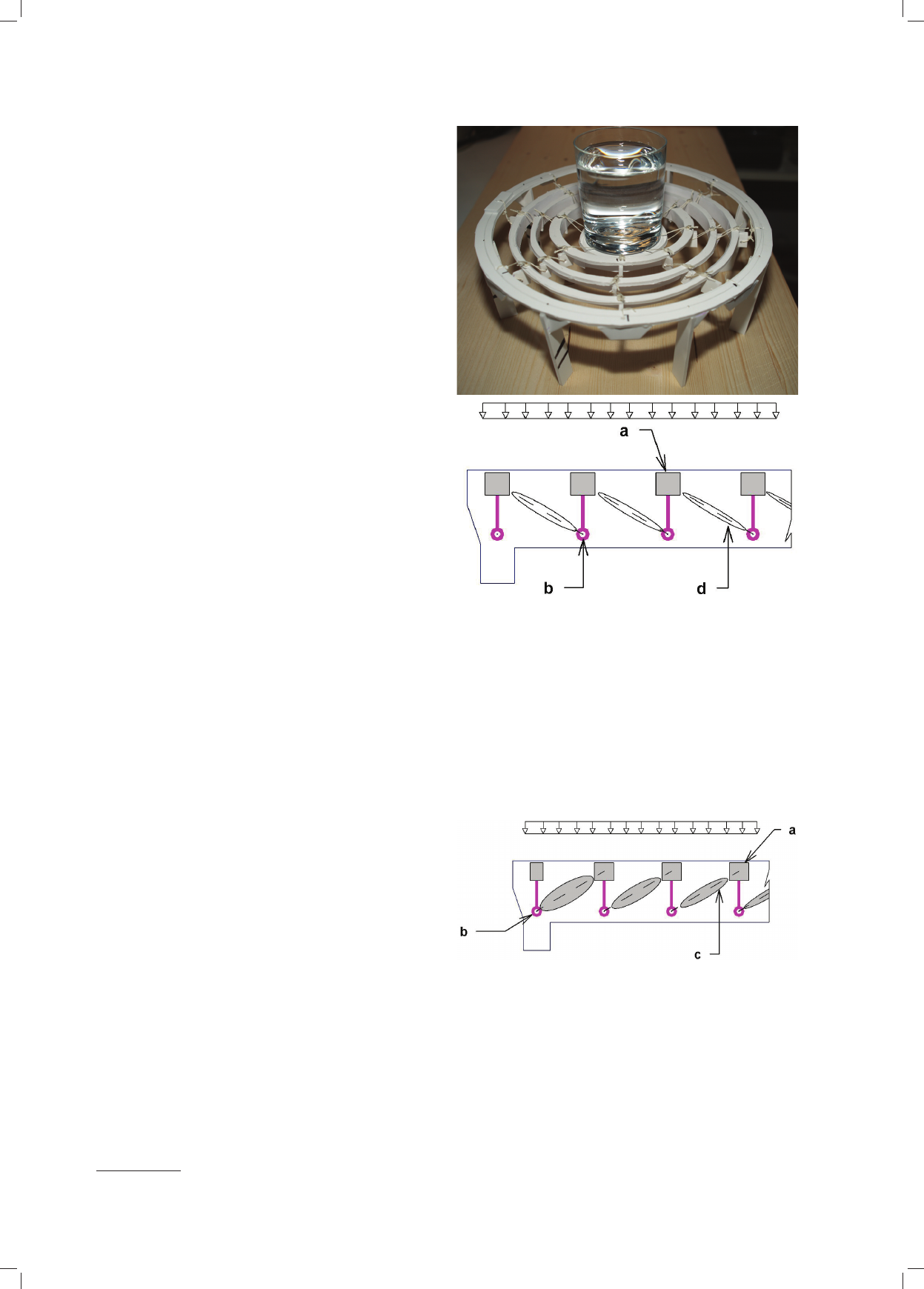
In the case of system “III” the ribs modelled from
the slab behave as the system of radial free-ends beams
intersecting with each other at the central point. Each of
them works independently, collecting the load from the
two wedge surfaces. The maximum moments occur at the
centre of the beam span (Fig. 5). Hence, the mass of mate-
rial creating the radial beam will be concentrated in the
central zone, further deepening the moments from the
external load. In such a solution there will be problems
with the physical construction of the central node.
Circumferential system “IV”
In the case of system “IV”, the circumferential ribb-
ing system carries the principal circumferential bending
moments as well as the horizontal and vertical com-
ponents of the adjacent rib reactions. In order to bet -
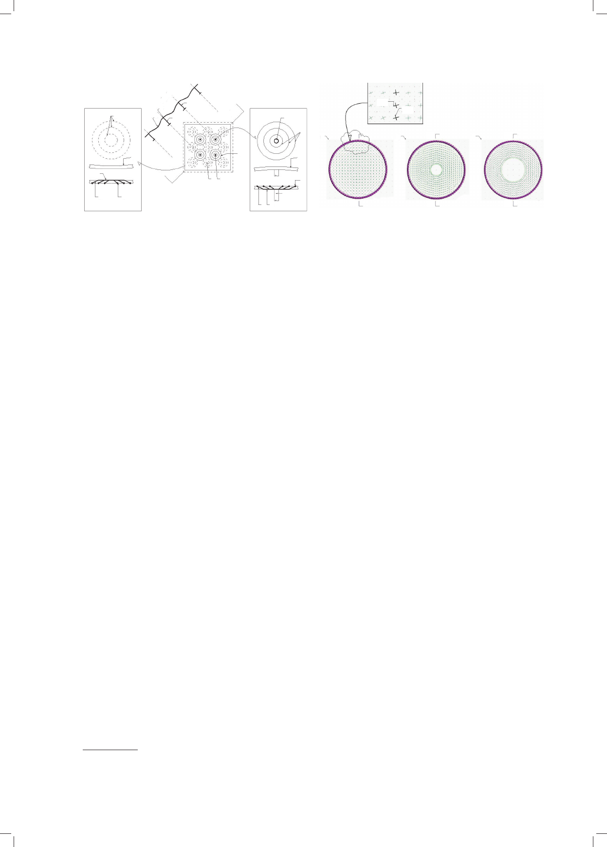
Il. 1. Schemat środkowy to rzut oraz diagonalny przekrój A-A płyty
opartej na słupach oraz przegubowo na krawędziach. Schematy „h, i”
przedstawiają deformację płyty płaskiej w obszarach „niecki” oraz
„czaszy” nad słupem. W schematach zastosowano zbrojenie płyty
prętami tworzącymi koncentryczne pierścienie kołowe. Kołowe linie
przerywane symbolizują tu zbro jenie dolne „a”, natomiast kołowe linie
ciągłe „b” symbolizują zbrojenie górne. Schemat lewy przedstawia
pracę kratownicową płyty, jaka generuje się w „niecce” płyty, schemat
prawy obrazuje pracę kratownicową płyty, jaka generuje się
w „czaszy” płyty nad słupem „c”. W obu przypadkach pierścienie
zbrojenia „a, b” łączone są z prętami strefy ściskanej „e”, krzyżulcami
betono wymi „d” powstającymi w materii tworzącej płytę żelbetową
zgodnie z teorią Morscha. Obszary czaszy wypukłej oznaczono jako
„g”, obszar czaszy wklęsłej „f”. Kontynuacja w podrozdziale System
równoleżnikowy „IV” (rys. autora)
Fig. 1. The middle diagram depicts the view and diagonal section A-A
of a slab supported on columns and pivotally on the edges.
Diagrams “h, i” depict the deformation of a flat slab in the regions
of a “trough” and “dome” above the column. The slab shown
in the diagrams is reinforced with bars forming concentric circular
rings. Circular broken lines “a” symbolize the lower reinforcement
and circular solid lines “b” symbolize the upper reinforcement.
The left diagram depicts the truss behaviour of the slab,
which is generated in the slab “trough”, the right diagram
depicts the truss behaviour of the slab, which is generated
in the slab “dome” above column “c”. In both cases the rings
of reinforcement “a, b” are joined with compression zone bars “e”
by concrete cross braces “d” created in the mass forming a reinforced
concrete slab according to Morsch’s theory. Convex dome areas are
marked as “g” and dished areas as “f”. To be continued in section
Circumferential system “IV” (drawn by the author)
Il. 2. Krzyże momentów głównych w płycie pełnej (e),
z małym otworem (g) i z dużym otworem (i). Widoczne są
dwa wzajemnie prostopadłe kierunki momentów głównych:
momentu równoleżnikowego (M1) oraz radialnego (M2).
Zauważyć można, że w płycie „e” krzyże momentów
równoleżnikowych i południkowych są równe sobie
w środkowej części płyty, po czym w miarę zbliżania się
do podpory momenty południkowe ulegają zmniejszeniu do zera.
W przypadku płyty z otworem „g” oraz „i” południkowe
momenty ulegają silnej redukcji, a momenty równoleżnikowe
silnej intensyfikacji (rys. autora)
Fig. 2. Visible crosses of the principal moments in a solid slab (e),
in a slab with a small hole (g), in a slab with a large hole (i).
The crosses represent the two (perpendicular to each other) directions
of the principal moments: the circumferential (M1) and radial moment
(M2). It is noticeable that in slab “e” the crosses of the circumferential
and radial moments are equal in the middle part of the slab and then,
as approaching the support, the meridional moments are reduced
to zero. In the case of a slab with a hole “g” and “i” the meridional
moments are strongly reduced and the circumferential moments are
strongly intensified (drawn by the author)
po wych
4
[2] omówiono bardziej szczegółowo. Celem
bar dziej przejrzystego zobrazowania pracy płyty zgina-
nej w analizie posłużono się również modelami rusz to-
wymi.
System ortogonalny lub diagonalny „II”
W przypadku systemu „II” płyta pracuje jak ruszt or-
togonalny, przy czym dla rzutów niekołowych ugięcia
rusztu diagonalnego będą mniejsze ze względu na
mniejsze rozpiętości belek. W związku z tym pochłoną
one mniej materiału konstrukcyjnego niż rozwiązania
ortogonalne. Zaletą systemów dwukierunkowych jest in-
tegracja belek podczas przenoszenia obciążeń nierówno-
miernych, zapewniająca ich wzajemną współpracę. Ko-
rzystna jest również stabilizacja pasów ściskanych.
4
Anizotropia oznacza tu zmienne własności płyty w zależności od
kierunku, w którym dana własność jest w nich obserwowana. Zarówno
zbrojenie, jak i użebrowanie zmieniają lokalnie sztywność płyty.
a
a c
c
c
c
c
b
i
i
b
b
A
A
A
A
A
A
f
g
g
M1
M2
A-A
A
A
h
e
e
e
d
d
a
72 Michał Pelczarski
System radialny „III”
W przypadku systemu „III” żebra wymodelowane
z płyty pracują jak układ belek radialnych, swobodnych,
przecinających się wzajemnie w punkcie centralnym.
Każ da z nich pracuje niezależnie, zbierając obciążenie
z dwóch powierzchni klinowych. Momenty maksymalne
występują w środku rozpiętości belek (il. 5). Stąd masa
materiału tworzącego belkę radialną będzie koncentrować
się w strefie środkowej, jeszcze bardziej pogłębiając mo-
menty od obciążenia zewnętrznego. Przy takim roz wią-
zaniu pojawią się trudności z fizycznym wykonaniem
węzła centralnego.
ter depict the behaviour of this interesting system, presented
below is an analysis of the diagrams of moments bending a
circular slab, the solid one and the one with a hole, from
uniformly distributed load (see also [4]). Possible system
configurations are further presented in detail.
• Meridional and circumferential bending moments
in “IV”-type systems
The approximate values of the circumferential mo -
ments can be found in section A-A according to the me -
thod presented in Figure 6. Knowing the value and loca-
tion of resultant “P” from load “q” acting on the cut-off
half of the slab and the location of the resultant arc sup-
port reaction “R”, it is possible to determine the bending
moments in the plane perpendicular to section A-A, as for
the cantilever beam [6]. Thanks to this the appro ximate
value of total concentrated moment Mc, is obtained and it
can be then distributed along the section length into
the
partial moments according to the proportion 1/3 to 2/3.
From the diagram of moments (M1) (perpendicular
to section A-A) bending the reinforced concrete slab in
the diametral section, it can be concluded that the lower
reinforcement rings will transfer the tensile forces aris-
ing from those moments and above them in the mass of
reinforced concrete the compression rings will form. As
the central bands are the longest they undergo bending to
the largest extent and, therefore, the inner rings will be
bent more strongly on a length of about 2/3 of the slab
diameter, which is visible in (Fig. 7 “f”
5
) [2], [4], [5],
[8], [9].
5
Diagrams from MES programme made by the author.
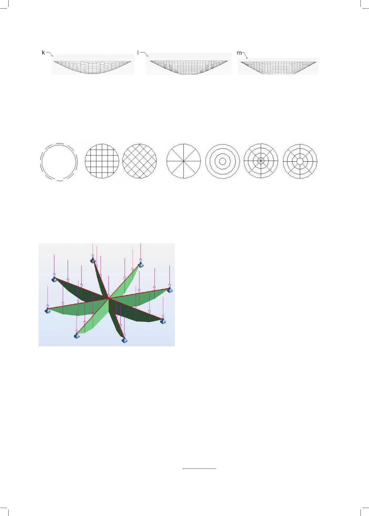
Il. 3. Widok boczny deformacji płyty bez otworu (k), z małym otworem (l) oraz z dużym otworem (m). Gdy skoreluje się deformacje z krzyżami
momentów głównych z ilustracji 2, zauważy się, że krzywizna południkowa jest tym większa, im większe są momenty główne – południkowe.
Ponieważ otwór zakłóca pracę układów południkowych, obserwuje się wypłaszczanie pasm południkowych w płytach z otworem (rys. autora)
Fig. 3. The side view of deformations in the slab without a hole (k), with a small hole (l) and with a large hole (m). When correlating the deforma-
tions with the crosses of the principal moments from Figure 2 it is noticeable that the meridional curvature is larger the larger the principal
meri dional moments are. As the hole upsets the behaviour of the meridional systems the flattening of meridional bands is observed
in the slabs with a hole (drawn by the author)
Il. 4.
Zastępcze konfiguracje systemów rusztowych lub żebrowych, modelujących pracę płyty opartej swobodnie na obwodzie:
system ortogonalny lub diagonalny (II), system radialny (III), system równoleżnikowy (IV), system radialno-równoleżnikowy (V),
system radialno-równoleżnikowy (VI)
z otworem (rys. autora)
Fig. 4. The diagram depicts the substitute configurations of grid or ribbed systems, modelling the behaviour of a slab freely supported
on the circum ference orthogonal or diagonal system (II), radial system (III), circumferential system (IV), radial and circumferential system (V),
radial and circum ferential system (VI) with a hole (drawn by the author)
Il. 5. Wykresy momentów zginających powstających w układzie radial-
nych belek obciążonych siłami skupionymi (rys. autora)
Fig. 5. The diagrams of bending moments generated in the radial
system of beams loaded with concentrated forces (drawn by the
author)
II III IV V VII
O kształtowaniu konstrukcji dachu katowickiej hali Spodka /About shaping the structure of Katowice Spodek-arena roof 73
• Possible configurations of “IV”-type
circumferential system
The system of concentric circumferential circles (type
„IV”) can be located in space in two different ways: by the
method of their suspending one from another (Fig. 8), and
by the method of their resting one against another (Fig. 9).
Each circle is a single dual ring consisting of two rings
connected with hangers: upper ring “a”, and lower ring “b”.
The first method involves suspending the successive
rings one from another by means of steel hangers (“d”)
or
other type of ties, as shown in Figure 8. The second
me thod involves supporting the rings one against another
by means
of cross braces (“c”) as shown in Figure 9.
In the case of a solid slab, by analogy to the beam, the
compression cross braces will form in the reinforced con-
crete mass.
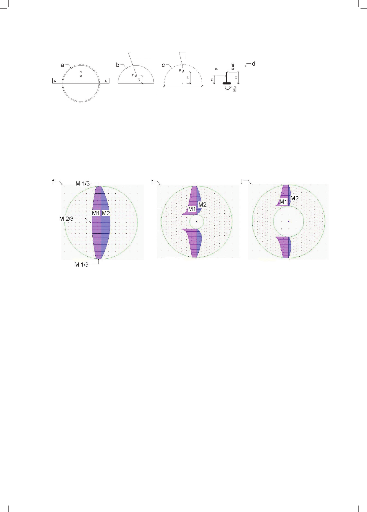
Il. 7. Wykresy momentów równoleżnikowych (M1) i południkowych (M2) w przekroju A-A dla płyty pełnej (f)
oraz z otworami (h) i (j). Momenty (M1) działają w płaszczyźnie prostopadłej do płaszczyzny przekroju A-A,
natomiast moment (M2) działa w płaszczyznach prostopadłych, do wirtualnie wyciętych, koncentrycznych przekrojów kołowych.
Na schematach „h, j” widoczny jest również wzrost momentów równoleżnikowych (M1),
będący wynikiem przerwania pasm środkowych, z których obciążenie przejmowane
jest przez nieco krótsze pasma sąsiednie (rys. autora)
Fig. 7. The diagrams present the graphs of circumferential moments (M1) and meridional moments (M2) in section A-A for a solid slab (f)
and for slabs with a hole (h) and (j). Moments (M1) act in the plane perpendicular to the plane of section A-A,
whereas moment (M2) acts in the planes perpendicular to imaginary concentric circular sections.
An increase in circumferential moments (M1), which is the result of discontinuation of central bands
and taking the load from them by slightly shorter adjacent bands is visible in diagrams “h, j” (drawn by the author)
Il. 6. Sposób wyznaczania mo -
mentu zginającego płytę w płasz-
czyźnie prostopadłej do przekroju
A-A [6]. To właśnie ten moment
przeno szony jest przez obręcze
współśrodkowe zbudo wane
z łą czonych wzajemnie słupkami
pierś cienia pasa górnego oraz
dolnego (rys. autora)
Fig. 6. The diagram presents the
method of determining the mo -
ment bending the slab in the
plane perpendicular to section
A-A. This is the very moment
carried by the concentric dual
rings consisting of an upper ring
and lower ring con nected with
each other by posts [6] (drawn by
the author)
Z1 = 2/3 × 2 r / π = 0,42 r
Z2 = 2 r / π = 0,63 r
P = q × (0,5 π × r × r)
M c = M całkowity = (P × Z2) - (P × Z1)
M c = M total = (P × Z2) - (P × Z1)
M średni rozłożony na długości średnicy = M całkowity / d
Average M distributed on the diameter lenght = M total / d
M2/3 = M rozłożony na 2/3 średnicy = 1,3 × M średni
M2/3 = M distributed on 2/3 of the diameter = 1.3 × M average
M1/3 = M rozłożony na 1/3 średnicy = M c – (1,3 M średni × 2/3 d) / 0,33 d
M1/3 = M distributed on 1/3 of the diameter = M c – (1.3 M average × 2/3 d) / 0.33 d
wypadkowa reakcji z podpory łukowej
resultant reaction from the arc support
wypadkowa obciążenia
resultant loading
System równoleżnikowy „IV”
W przypadku układu typu „IV” to system użebrowania
równoleżnikowego przenosi główne, równoleżnikowe
momenty zginające oraz składowe poziome i pionowe
oddziaływań sąsiednich żeber. Aby lepiej zobrazować
pra cę tego ciekawego systemu, dalej przedstawiono ana-
lizę przebiegu momentów zginających płytę kołową
pełną oraz z otworami, od obciążenia równomiernie roz-
ło żonego [4]. Dalej zaprezentowano też szcze gółowo
możliwe konfiguracje systemu.
• Momenty zginające południkowe i równoleżnikowe
w systemach typu „IV”
Przybliżone wartości momentów równoleżnikowych
widać w przekroju A-A płyty według metody przedsta-
wionej na ilustracji 6. Znając wartość oraz odległość wy-
74 Michał Pelczarski
pad kowej „P” od obciążenia „q” działającego na odciętą
połowę płyty oraz położenie wypadkowej reakcji podpo-
ry łukowej „R”, można wyznaczyć momenty zginające,
w płaszczyźnie prostopadłej do przekroju A-A, jak dla
belki wspornikowej [6]. Dzięki temu uzyskuje się przy-
bliżoną wartość całkowitego momentu skupionego Mc,
który następnie można rozłożyć na długości przekroju na
momenty cząstkowe według proporcji 1/3 do 2/3.
Z przebiegu momentów (M1) (prostopadłych do prze-
kroju A-A) zginających badaną płytę żelbetową w przek-
roju średnicowym można wywnioskowa
ć, że dolne pierś-
cienie zbrojenia przenosić będą siły rozciągające pow-
stające od tych momentów, a nad nimi w masie żel betu
wyt worzą się pierścienie ściskane. Ponieważ pasma środ-
kowe są najdłuższe, ulegają największemu zginaniu,
w związ ku z czym pierścienie wewnętrzne będą silniej
zgi nane na odcinku bliskim 2/3 średnicy płyty, co widocz-
ne jest na ilustracji 7f
5
[2], [4], [5], [8], [9].
• Możliwe konfiguracje systemu równoleżnikowego
typu „IV”
System współśrodkowych kół równoleżnikowych
(typu „IV”) umiejscowić można wzajemnie w przestrzeni
na dwa sposoby: metodą ich wzajemnego podwieszania
(il. 8) oraz metodą ich wzajemnego opierania (il. 9).
Każde koło to pojedyncza obręcz składająca się z dwóch
połączonych wieszakami pierścieni – górnego „a” oraz
dol nego „b”. Pierwsza metoda polega na wzajemnym
pod
wieszeniu
kolejnych obręczy za pomocą stalowych
wieszaków („d”) lub innego rodzaju cięgien. Tak jak na
ilustracji 8. Drugi sposób polega na wzajemnym podpar-
ciu pierścieni za pośrednictwem krzyżulców (c”), jak na
ilustracji 9. W przypadku płyty pełnej analogicznie jak
w belce krzyżulce ściskane tworzą się w ma terii żelbetu.
Podsumowując, w obu typach konfiguracji obciążonych
grawitacyjnie górne obręcze równoleżnikowe („a”) prze-
noszą ściskania osiowe, a obręcze dolne („b”) prze noszą
rozciągania osiowe. Momenty równoleżnikowe i pow -
stające od nich pary sił przedstawiono na ilustracji 10g, h.
W obu też przypadkach obręcze górne („a”) pracują
jako opory dla poziomych składowych południkowych sił
„f” (il. 10) działających obwodowo. Dążą one do zm-
niejszenia średnic tych obręczy, co prowadzi do dalszego
wzros tu ściskania osiowego obręczy górnych „a”. Ana lo-
gicz nie, lecz jako rozciągane opory, dla poziomych skła do-
wych sił „e” pracują obręcze dolne „b”, jak na ilustracji 10.
Ostatecznie więc obręcze „a” ściskane są siłami od rów no-
leżnikowego momentu zginającego oraz dodatkowo
ściskane od poziomych składowych ciągnień „f”. W przy-
padku pierścieni „b” są one rozciągane siłami wywo
łanymi
zginaniem od momentu równoleżnikowego oraz do datko-
wo
rozciągane od poziomych składowych ciągnień „e”.
System radialno-równoleżnikowy „V”
W przypadku konfiguracji typu „V” schemat pracy
płyty jest połączeniem przypadku „III” oraz „IV”. Dlatego
też wprowadzając zbrojenie naśladujące układy głównych
5
Wykresy z programu MES, wykonane przez autora.
Il. 9. Schemat przedstawia zasadę pracy systemu równoleżnikowego,
gdy obręcze równoleżnikowe ulokowane koncentrycznie
są wzajemnie podparte krzyżulcami „c”.
W przypadku płyt żelbetowych krzyżulce wytworzą się
z masy betonu tworzącego płytę analogicznie
do systemu kratownicy Morscha. Pierścienie górne oznaczono
jako „a”, dolne jako „b” (rys. autora)
Fig. 9. The diagram depicts the principle of circumferential system
behaviour when the concentrically located circumferential rings
are supported one against another by means of cross braces “c”.
In the case of reinforced concrete slabs, the cross braces
are formed in the concrete mass by analogy to Morsch’s truss system.
Upper ring was marked as “a” and lower rings as “b”
(drawn by the author)
Il. 8. Model obciążonego systemu równoleżnikowego – protoplasty
systemu tensegrity. Schemat dolny prezentuje zasadę pracy systemu
równoleżnikowego. Obręcze równoleżnikowe ulokowane koncen-
trycznie składają się z pierścienia górnego „a” oraz dolnego „b”
i są wzajemnie podwieszone poprzez wieszaki „d” (rys. autora)
Fig. 8. The photograph shows a model of the loaded circumferential
system – an ancestor of the tensegrity system. The lower diagram
depicts the principle of circumferential system behaviour.
The concentrically located circumferential rings consist of an upper
ring “a” and lower ring “b” and are suspended one from another by
means of hangers “d” (drawn by the author)
O kształtowaniu konstrukcji dachu katowickiej hali Spodka /About shaping the structure of Katowice Spodek-arena roof 75
sił rozciągających w płycie żelbetowej, w strefie dolnej
trzeba zastosować układy prętów równoleżnikowych „b”
oraz radialnych „e” (il. 11). W strefie górnej przekroju
betonowego powstaną analogiczne, lecz ściskane pasma
równoleżnikowe i południkowe „a, c”.
W przypadku pracy rusztu belkowego o geometrii typu
„V” można zauważyć, że elementy równoleżnikowe
pełnią funkcję wspomagającą – odciążają zginane belki
radialne. Ponieważ belki równoleżnikowe obracają się
swobodnie w węzłach wraz z uginającymi się belkami
radialnymi, nie powstają w nich momenty skręcające.
W poszczególnych węzłach siły ściskają
ce z pasa gór-
nego belek radialnych wnikają w pasy górne belek rów-
no leż nikowych. Analogicznie dzieje się na poziomie pasa
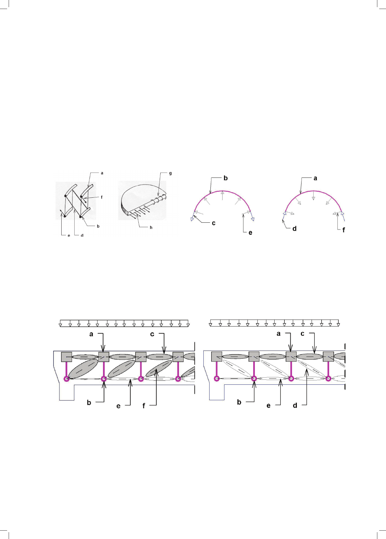
Il. 10. Schematy wyjaśniające zasadę pracy pierścieni oporowych „a, b”. Pierścień „a” poddany działaniu radialnych ciągnień od składowej
poziomej „f” ulega dalszemu ściskaniu osiowemu, natomiast pierścień „b” poddany przeciwnemu radialnemu działaniu „e”
podlega dalszemu rozciąganiu osiowemu. Mechanizm ten obrazują również zwroty reakcji „c” i „d” powstające w przekrojach pierścienia.
Momenty równoleżnikowe w przekroju oznaczono jako „g”, natomiast pary sił osiowych od tych momentów pochodzące oznaczono jako „h”
(schemat lewy: W.Z., prawy: autor)
Fig. 10. The diagrams explain the behaviour of thrust resistance rings “a, b”. Ring “a” subjected to action of radial pulling forces
from the horizontal component of “f” undergoes further axial compression, whereas ring “b” subjected to the opposite radial action of “e”
undergoes further axial tension. This mechanism is also depicted by the senses of reactions “c” and “d” forming in the ring sections.
The circumferential moments in the section have been marked as “g”, while the pairs of axis forces originating from these moments
have been marked as “h” (left diagram: W.Z., right: drawn by the author)
Il. 11. Możliwe konfiguracje systemu typu „V” przenoszącego momenty zarówno radialne, jak i południkowe.
Porównując schemat lewy z prawym, układy obręczy zbudowanych ze ściskanych pierścieni „a” i rozciąganych pierścieni „b”
połączonych rozciąganymi słupkami są tu jednakowe. Jednakowe są też ściskane pasy górne „c” i pasy dolne rozciągane „e”.
Różnica dotyczy tylko sposobu przenoszenia momentów poł
udnikowych. Lewy układ wykorzystuje ściskane krzyżulce „f”, natomiast prawy
układ wykorzystuje krzyżulce rozciągane „d”. W przypadku płyt żelbetowych krzyżulce betonowe wytworzą się z masy betonowej,
natomiast w przypadku rozwiązania prawego konieczne jest wbudowanie do płyty stalowych diagonali lub pochylonych strzemion (rys. autora)
Fig. 11. The diagrams depict the possible configurations of system “V” transferring both radial and meridional moments.
Comparing the left diagram with the right one, the systems of rings consisting of compression rings “a” and tension rings “b”
connected with the tension posts, are the same. Likewise, upper compression strips “c” and lower tension strips “e” are equal.
The only difference is in the way of transferring the meridional moments. The left system employs compression cross braces “f”
whereas the right system employs tension cross braces “d”. In the case of reinforced concrete slabs, concrete cross braces will form
from the concrete mass, while in the case of the right solution it is necessary to embed steel diagonals or inclined stirrups in the slab
(drawn by the author)
To sum up, in both configuration types, gravitationally
loaded, the upper circumferential rings (“a”) carry axial
compressions and the lower rings (“b”) carry axial ten-
sions. The circumferential moments and related couples
of forces are depicted in Figure 10 “g, h”.
In both cases, the upper rings (“a”) act as stops for the
horizontal components of meridional forces “f” (Fig. 10)
acting circumferentially. They tend to decrease the diam-
eters of those rings, which leads to a further increase in
the axial compression of upper rings “a”. By analogy, the
lower rings “b” work as pulled stops for the horizontal
components of forces “e”, as shown in Figure 10.
Eventually, rings “a” are compressed by the forces
from the circumferential bending moment and, in addi-
76 Michał Pelczarski
dolnego. Skutkiem tego w belkach równoleżniko wych
pow stają momenty zginające, a od obciążeń symetrycz-
nych są stałe na całym obwodzie pierścienia.
System radialno-równoleżnikowy typu „VI”
z otworem
W przypadku wykonania otworu centralnego w ruszcie
typu „VI” belki południkowe ulegają przerwaniu i pierś-
cienie równoleżnikowe pełnią wówczas niezbędną
funkcję nośną – wspierającą końce żeber radialnych.
Rozwiązanie z otworem daje możliwość budowy
świet lika centralnego. Moment na wewnętrznym końcu
bel ki radialnej równoważony jest przez momenty pow-
stające w elementach dochodzących z obu stron pierście-
nia. Ponieważ moment radialny musi zostać zrównowa-
żony dwo ma jednakowymi momentami równoleż ni ko-
wymi, momenty te będą tym większe, im większy będzie
kąt rozwarcia między radialnymi elementami tworzącymi
pierścień.
Przekrycie typu tensegrity
Możliwe jest również zastosowanie systemu podwie-
szanego typu „IV” z usunięciem ściskanych pierścieni
górnych (il. 12). System ulega tu zmianie z układu prze-
noszącego momenty zginające (charakterystycznego dla
płyty sztywnej) na system podwieszony. Układ taki cha-
rakteryzuje się niskim wskaźnikiem ciężaru własnego, ale
ma duże odkształcenia lokalne od obciążeń niesymetrycz-
nych. Dlatego najodpowiedniejsze dla tego typu kon-
strukcji jest stosowanie pokrycia membranowego.
Rolę głównego nośnika obciążenia przejmuje tu system
rozciąganych dolnych obręczy „b”, podwieszonych
wzajem nie za pomocą radialnych lin „d” kotwionych
w po jedynczym ściskanym pierścieniu zewnętrznym „i”
(il. 12).
tion, they are compressed by the horizontal components
of pulling forces “f”.
In the case of rings “b” they are pulled by the forces
generated by bending from the circumferential moment
and, in addition, they are pulled by the horizontal compo-
nents of pulling forces “e”.
Radial-circumferential system “V”
In the case of “V”-type configuration, the diagram of
slab behaviour is the combination of cases “III”
and “IV”. Therefore, in order to apply reinforce ment
simula ting the system of principal tensile forces in a rein-
forced concrete slab, the systems of equipotential
bars “b” and radial bars “e” (Fig. 11) must be applied.
By analogy, equipotential and meridional compression
bands “a, c” will form in the upper zone of the concrete
section.
In the case of a beam grid with the “V”-type geomet-
ry it is noticeable that the circumferential members per-
form an assisting and relieving function for the bent
radial beams. As the circumferential beams rotate freely in
the nodes together with the bent radial beams, no torsio-
nal moments are formed in them. In particular nodes the
compressive forces from the upper strip of radial beams
penetrate the upper strips of circumferential beams. The
same happens at the lower strip level. As a re sult, bending
moments are formed in the circumferential beams, and
those from the symmetrical loads are constant on the
whole circumference of the ring.
Radial-circumferential system “VI”
with a hole
In the case when there is a central hole in the “VI”-
-type grid, the meridional beams are discontinued and
then the circumferential rings perform the necessary load-
carrying function – supporting the ends of the ra dial
ribs.
The solution with a hole offers the possibility of con-
structing a central skylight. The moment at the inner end
of the radial beam is counterbalanced by the moments
generated in the members coming from both sides of the
ring. As the radial moment must be counterbalanced by
the two identical circumferential moments, these moments
will be greater the greater is the angle between the ring-
forming radial members.
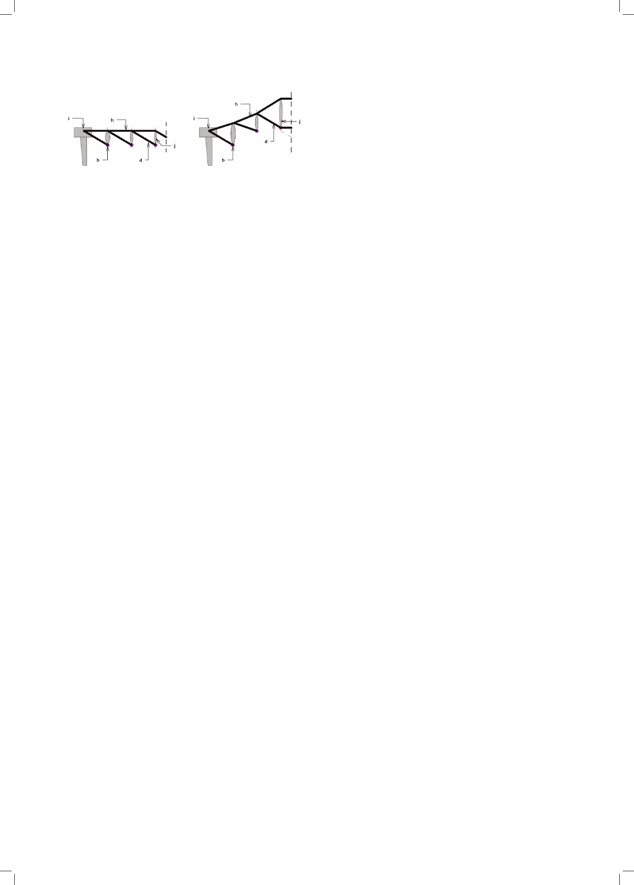
Tensegrity-type cover
It is also possible to apply the “IV”-type suspended sys-
tem with the upper compression rings removed (Fig. 12).
The system will change from a bending moment trans ferring
system (characteristic of the rigid slab) into a sus pended
system. Such a system is characterised by a low deadweight
index, but features large local deflections from asym-
metrical loads. Therefore, the application of a membrane
cover is the most suitable for this type of structure.
The role of the principal load carrier is taken over here
by the system of lower tension rings “b”, suspended one
from another by means of radial cables “d” anchored in
the single external compression ring “i” (Fig. 12).
Il. 12. Z lewej płaska wersja systemu tensegrity. Z prawej bardziej
znany system kopuły w systemie tensegrity. Płaska wersja wymaga
dociążenia balastem, np. ciężarem świetlika, ze względu na
mniejszą odporność na obciążenia od ssania wiatru spowodowaną
mniejszymi kątami między elementami linowymi prowadzącymi
do powstawania większych sił i odkształceń Pierścień dolny „b”,
podporowy pierścień zewnętrzny „i”, radialne liny podwieszające „d”,
pionowy słupek – dewiator, pas górny „h”
(rys. autora)
Fig. 12. On the left, the flat version of the tensegrity system. On the
right, the better known dome system in the tensegrity system. The flat
version requires loading with ballast – e.g. with a skylight due to the
smaller resistance to loads from the wind suction caused by the smaller
angles between the cable members leading to the formation
of larger forces and deflections. Lower ring was marked as “b”,
supporting external ring as “i”, radial hanging elelments “d”,
vertical colums, top chord “h” (drawn by the author)
O kształtowaniu konstrukcji dachu katowickiej hali Spodka /About shaping the structure of Katowice Spodek-arena roof 77
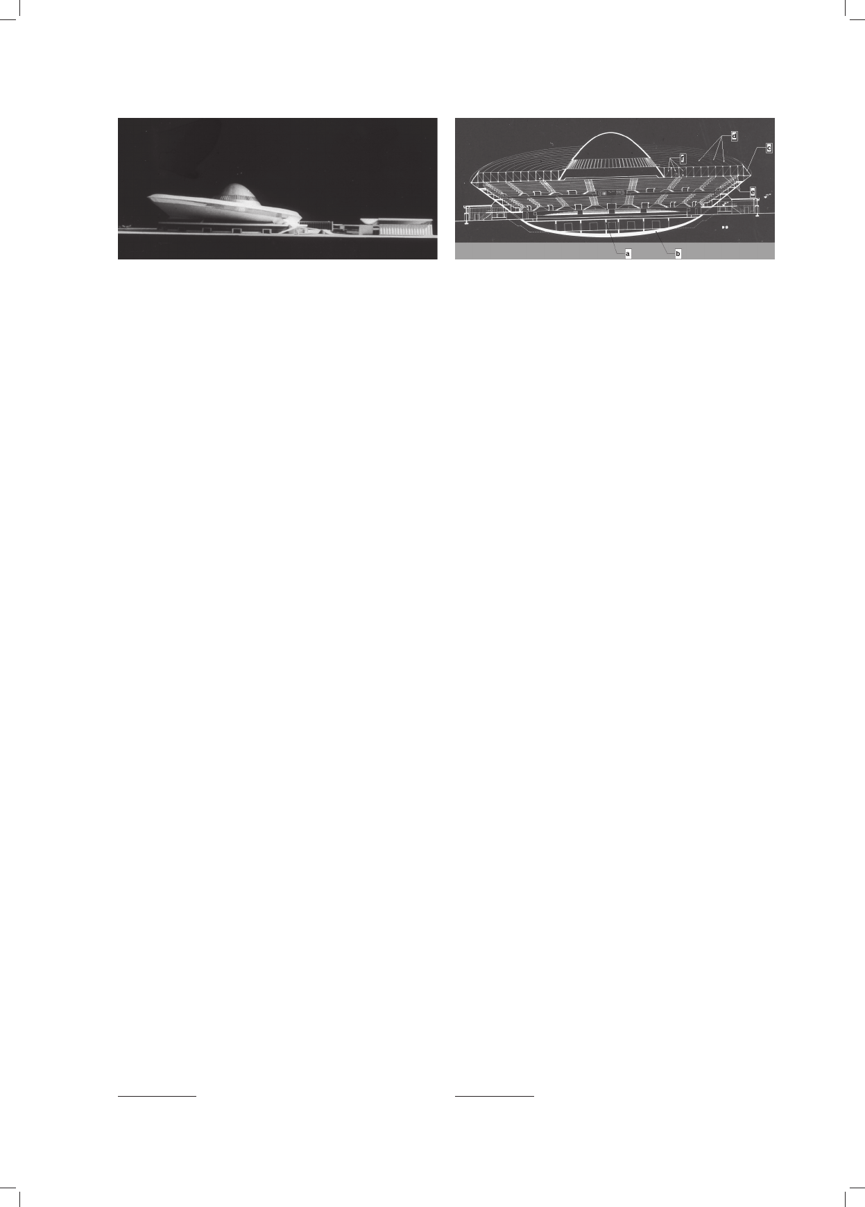
Stages of shaping the form
and structural solutions of the Spodek hall
On the complex design of the Spodek and degree of
di ffi culty of the creation process of this construction
maybe attes ted by the model of the hall presented in illus-
trations 13 and 14.
Solutions proposed
by Professor Zalewski
As a supporter of the “clear function architecture”
de sign Prof. Zalewski designed a characteristic conical
geo metry for the hall auditorium. The shell foundation
with a box bottom “a” (Fig. 14) was its integral part allo-
wing “floating of the hall as a ship”
6
in a weak soil [3].
For the roof structure, W.Z. proposed a “IV”-type sys-
tem (Fig. 4) of concentric, rings “d” (Fig. 14) suspended
one from another by means of hangers “f” and eventually
anchored to the external ring “c”. One of the basic reasons
for such shaping was the need to create a circular hole for
a skylight dome, free from structural members.
In order to persuade the investor to accept his innova-
tive idea, Prof. Zalewski proved that the material volume
would be exactly the same as for the “III”-type radial
truss system and for its “IV”-type ring system.
As the load-carrying system separated from the solid
slab is sensitive to concentrated loads, both in the model
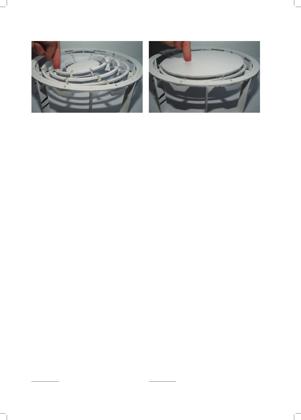
and design, a rigid disc (Fig. 15) covering the rings was
assumed for the roof in order to control the deformations
of the system from non-uniform loads.
Changes in the original
design conditions
Initially the Spodek roof was to be horizontal – how-
ever, its inclination was determined due to architectural as
well as functional reasons concerning the stage and the
auditorium in which the main axis with the best visibility
was accentuated when preparing a backroom for the stage
in the low part of the building.
6
A citation from an interview with Prof. Wacław Zalewski.
Etapy kształtowania formy i rozwiązań
konstrukcyjnych hali Spodka
O złożoności projektu Spodka i stopniu trudności pro-
cesu tworzenia tej konstrukcji może świadczyć już sam
model hali przedstawiony na ilustracji 13 i 14.
Proponowane rozwiązania Wacława Zalewskiego
Profesor, będąc zwolennikiem projektowania „archi-
tektury czytelnej funkcji”, przewidział dla hali cha rak-
terystyczną stożkową geometrię widowni. Integralną jej
częścią był fundament powłokowy z dnem skrzyniowym
„a” (il. 14), umożliwiający „pływanie hali niczym okręt”
6
w słabym gruncie [3].
Dla konstrukcji dachu zaproponował system typu „IV”
(il. 4) – koncentrycznych pierścieni „d” (il. 14) podwie-
szonych wzajemnie za pośrednictwem wieszaków „f”
i kot wionych ostatecznie do pierścienia zewnętrznego
„c”. Jedną z zasadniczych przyczyn takiego kształtowania
podjętego przez Profesora była potrzeba wytworzenia
kołowego otworu na kopułę świetlika, wolnego od ele-
mentów konstrukcyjnych.
Celem przekonania inwestora do swego nowatorskiego
pomysłu W. Zalewski dowiódł, że objętość materiału bę-
dzie dokładnie jednakowa dla systemu radialnych kra-
townic typu „III” oraz systemu jego pierścieni typu „IV”.
Ponieważ układ nośny wyseparowany z płyty pełnej
jest wrażliwy na obciążenia skupione w modelu, założono
sztywną tarczę jak w projekcie pierwotnym (il. 15) dachu,
pokrywającą pierścienie, która kontroluje deformacje
układu od nierównomiernych obciążeń.
Zmiany warunków pierwotnych projektu
Początkowo dach Spodka miał być poziomy – jed-
nakże o jego pochyleniu zdecydowały względy architek-
toniczne oraz funkcjonalne organizacji sceny i widowni,
w której zaakcentowano oś główną o najlepszej widocz-
ności, przy gotowując zaplecze sceny w niskiej części
obiektu.
6
Cytat z wywiadu autora z prof. Wacławem Zalewskim.
Il. 14. Przekrój Spodka w wersji konkursowej przedstawia oryginalne
rozwiązanie konstrukcji przekrycia autorstwa W. Zalewskiego
(zdjęcie z archiwum W.Z.)
Fig. 14. The section of Spodek in the contest version
shows the original structural solution for the cover
developed by W. Zalewski
(the photograph comes from W.Z. archives)
Il. 13. Model zwycięskiej koncepcji zrealizowanej w zespole
W. Zalewskiego w konkursie SARP-u na projekt hali sportowej
w Katowicach w 1959 r. (zdjęcie z archiwum W.Z.)
Fig. 13. The view of the winning concept developed
by W. Zalewski’s team in the SARP contest
for the design of a sports hall in Katowice in 1959
(the photograph comes from W.Z. archives)
78 Michał Pelczarski
W konsekwencji geometrię obiektu stanowi odwróco-
ny stożek o podstawie przyciętej płaszczyzną nachyloną
pod kątem około 5,7 stopnia. Z kołowego więc dachu
w wersji dachu poziomego utworzył się dach o kształcie
eliptycznym. W tej konfiguracji Profesor przearanżował
układy pierścieni w taki sposób, by oś kopuły świetlika
umieszczona była nad środkiem boiska oraz by jej kra-
wędź dolna była kołowa. Wymogi te oraz pochylenie
dachu mocno skomplikowały układ kołowych pierścieni,
które wpisywane mimośrodowo w elipsę musiały ulegać
przerywaniu w miejscach „wtapiania” się kół w elipsę.
Pierwotnie hala miała być lokalizowana w pobliżu cen-
trum na terenie o bardzo słabej nośności gruntu, jednakże
ostatecznie przeniesiona została do ścisłego centrum Ka to-
wic przy skrzyżowaniu dwóch ważnych arterii aglomera-
cji. Nowe warunki gruntowe były jeszcze bardziej skom-
pli kowane, ze względu na szkody górnicze i bez poś rednią
bliskość czynnej kopalni węgla kamiennego „Kleofas”.
Prze widywano możliwość wystąpienia: lokalnych zapad-
lisk, nieciągłości krzywizny terenu, nierównomiernego
osia dania spowodowanego różnymi grun tami skalistymi
oraz piaszczystymi, rozpełzania gruntu w płaszczyznach
równoległych do osi głównej lub w płaszczyznach odchylo-
nych o 30 stopni od tego kierunku, a także możliwości
wystąpienia wygięcia terenu ku górze. Badania wykazały
również występowanie masywu skalnego zalegającego
w osi hali. Z powodu spodzie wanych deformacji górni-
czych fundament musiał mieć minimalną powierzchnię
styczności z gruntem. Jego wnętrze musiało zostać otwarte
z powodu sztywnego ma sywu skalnego, który występował
w nowej lokalizacji. Do datkowym czynnikiem komplikują-
cym rozwiązanie konstrukcyjne fundamentów było to, iż
geometria wsporników dachu „m” (il. 16) mocowanych
w żebrach widowni wymuszała odległe od źródeł obcią-
żenia podparcie fundamentowe. Ostatecznie więc przyjęto
bardzo oryginalne rozwiązanie reagujące aktywnie na
defor mację terenu niczym „okręt unoszący się na fali”
7
lub
ra czej swo bodnie ją przepuszczający pod sobą.
7
Z wywiadu autora z prof. inż. arch. Henrykiem Buszko.
As a consequence the object geometry is a reverse cone
with its base inclined at an angle of approx. 5.7 de grees.
Thus, a circular roof in the horizontal roof version
changed its shape into an elliptic one. In this configuration
W.Z. rearranged the system of rings in such a way that the
axis of the skylight dome would be located above the
cen
tre of the playing area and that its lower edge would be
circular. Those requirements and the roof inclination
strongly complicated the system of circular rings
which as being inscribed into an ellipse had to be dis-
continued in certain places where the circles “blend” into
the ellipse.
Originally the hall was to be located near the city cen-
tre on soils with a low bearing capacity, however, it was
eventually moved to the close vicinity of the centre of
Katowice at the intersection of the two arterial roads of
the agglomeration. The new soil conditions were even
more complicated due to mining damage and the direct
vicinity of productive coalmine “Kleofas”. It was antici-
pated that the following might occur: local sink holes,
ground surface curvature discontinuity, non-uniform
ground subsidence caused by different rock and sand
soils, soil creep in planes parallel to the main axis or in
planes inclined at 30 degrees from that direction as well
as an up-warp of the ground surface. The research had
also revealed the occurrence of rock massif in the hall
axis. Owing to the expected mining deformations, the
foun dation had to have the minimum contact surface with
the ground. Its interior had to be opened due to the rigid
rock massif which occurred in the new location. Another
factor which complicated the structural solution of the
foundation was the fact that the geometry of roof brackets
“m” (Fig. 16) mounted in the auditorium ribs forced the
foundation support away from load sources. Thus, even-
tually, a very original solution actively reacting to the
ground surface deformation as “a ship floating on
a wave”
7
or rather passing it freely underneath was
adopted.
7
From an interview with architect Prof. Henryk Buszko.
Il. 15. Zdjęcia przedstawiają wrażliwość na deformacje układu pierwotnego tensegrity pod niesymetrycznym obciążeniem siłą skupioną.
Po zastosowaniu sztywnej płyty pokrycia problem ten zostaje zlikwidowany (fot. M. Pelczarski)
Fig. 15. The photos show the original tensegrity system sensitivity to deformations under the load of an assymmetric concentrated force.
After the application of a rigid cover plate the problem becomes resolved (photo by M. Pelczarski)
O kształtowaniu konstrukcji dachu katowickiej hali Spodka /About shaping the structure of Katowice Spodek-arena roof 79
Final solutions for the Spodek hall
cover structure
Finally, when Prof. Zalewski was already outside the
Polish borders the design team composed of, inter alia,
Andrzej Żórawski [10], [11], arch. Maciej Gintowt and
Maciej Krasiński decided to apply the cover system com-
prising a system of flat cable-strut girders. This system
was probably easier to develop in the inclined roof with
an elliptic outline. It was also easier because the girder
solution had been probably adapted from the earlier
designs of experimental industrial building.
Therefore, the roof structure was divided into two
areas: the circular part in which 120 identical cable-strut
girders were spanned, and bracket part “m” to fill up to
the elliptic outline (Fig. 16).
The diagram (Fig. 17) presents the general principle of
the cable-strut girder system. The sketches in (Fig. 18)
show the two possible solutions for this type of girders.
A solution with inclined posts was applied in the Spodek
and presented below is a description of structural behav-
iour and construction of these girders.
The complex of radial cable-strut systems suspended
from each other and anchored in the external ring was
obtained after giving up the lower circumferential rings
(“b”) of the tensegrity system and replacing them with the
radial cables “ł” of the lower belt (Fig. 17).
However, the application of continuous cable members
“k” (Fig. 18) running without resistance through interme-
diate nodes “m” requires that cable spacing posts “j” must
Ostatecznie zrealizowane rozwiązania
konstrukcji przekrycia hali Spodka
Ostatecznie, gdy Profesor był już poza granicami Pols-
ki, zespół projektowy w składzie m.in. inż. Andrzej Żóra-
w ski [10], [11], arch. Maciej Gintowt oraz arch. Maciej
Kra siński zdecydowali o zastosowaniu systemu przekry-
cia składającego się z układu płaskich dźwigarów prę-
towo-cięgnowych. Był to najprawdopodobniej system łat-
wiej szy do realizacji w odchylonym od poziomu dachu,
dodatkowo posiadającym obrys eliptyczny. Łatwiejszym
rów nież dlatego, że rozwiązanie dźwigara zaadaptowano
prawdopodobnie z wcześniejszych realizacji eksperymen-
talnego budownictwa przemysłowego (il. 16).
W związku z powyższym konstrukcję dachu podzielo-
no na dwa obszary: część kołową, w której rozpięto
120 jed nakowych prętowo-cięgnowych dźwigarów, oraz
część wspornikową „m”, dopełniającą do obrysu eliptycz-
nego (il. 16).
Na schemacie (il. 17) przedstawiono ogólną zasadę
pracy dźwigarów prętowo-cięgnowych. Na ilustracji 18
za prezentowano dwa możliwe rozwiązania tego typu
dźwi garów. W Spodku zastosowano rozwiązanie z po-
chylonymi słupkami. Poniżej opisano schemat pracy i bu-
do wy tych dźwigarów.
System radialnych układów prętowo-cięgnowych prze-
wieszonych na sobie wzajemnie i kotwionych w pierś-
cieniu zewnętrznym uzyskano po rezygnacji z dol nych
pierścieni równoleżnikowych „b” systemu tensegrity i zas-
tąpieniu ich linami radialnymi pasa dolnego „ł” (il. 17).
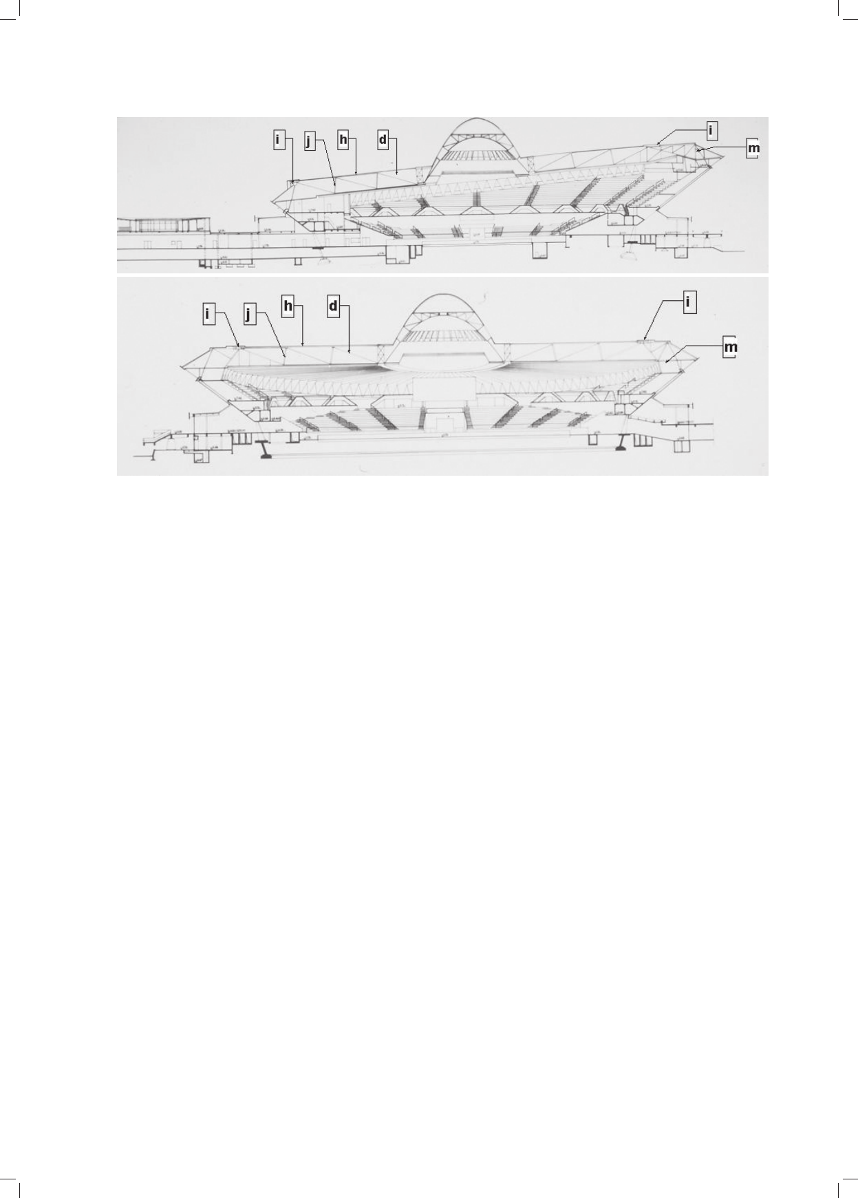
Il. 16. Dwa główne przekroje istniejącej konstrukcji hali katowickiego Spodka. 120 jednakowych płaskich dźwigarów prętowo-cięgnowych „d, h,
j” kotwionych jest w pierścieniu kopuły świetlika oraz w zewnętrznym pierścieniu „i”. Pierścień zewnętrzny ma geometrię kołową, a ze względu
na eliptyczny obrys krawędzi dachu spoczywa on na wspornikowych kratownicach „m” o zmiennych wysięgach (schemat z archiwum W.Z.)
Fig. 16. The two main sections of the existing structure of the Spodek hall in Katowice. 120 identical flat cable-strut girders “d, h, j” are anchored
in the skylight dome ring and in external ring “i”. The external ring has a circular geometry and due to an elliptic outline of the roof edge it rests
on truss brackets “m” with variable spans (drawing scheme from W.Z. archives)
80 Michał Pelczarski
be situated in the bisector of the angle between them. The
force in the cable tends to equalise its value before the
node and after the nodes so a deviator post will be pushed
into the axis of the resultant force, i.e. the equilibrium
po sition.
Conclusions – historical background
The considerations presented in this article mainly con-
cerned the phases of shaping the roof structure of the
Spodek hall and did not touch upon the equally interesting
system of its foundations. There is no doubt, however, that
no similar object has been so far built in the world and its
architectural form as well as many of the applied solutions
are unique on a global scale. Beyond the shadow of doubt,
the design of the Spodek hall structure should be regarded
as extremely bold and exceptional for those times but
what is more important for the present times as well.
The hall was under construction for nearly 10 years in
a reality when the computers were still fledging and in the
conditions of political tensions between the central
authority and the authorities of the Upper Silesia region.
Invalu able support for the undermined investment was
provided by General Jerzy Ziętek who, during the years
1964–1973, was the chairman of the Presidium of the
Voivodeship Coun cil in Katowice
8
. An anecdote says
8
http://pl.wikipedia.org/wiki/Jerzy_Zi%C4%99tek [accessed:
28.05.2013].
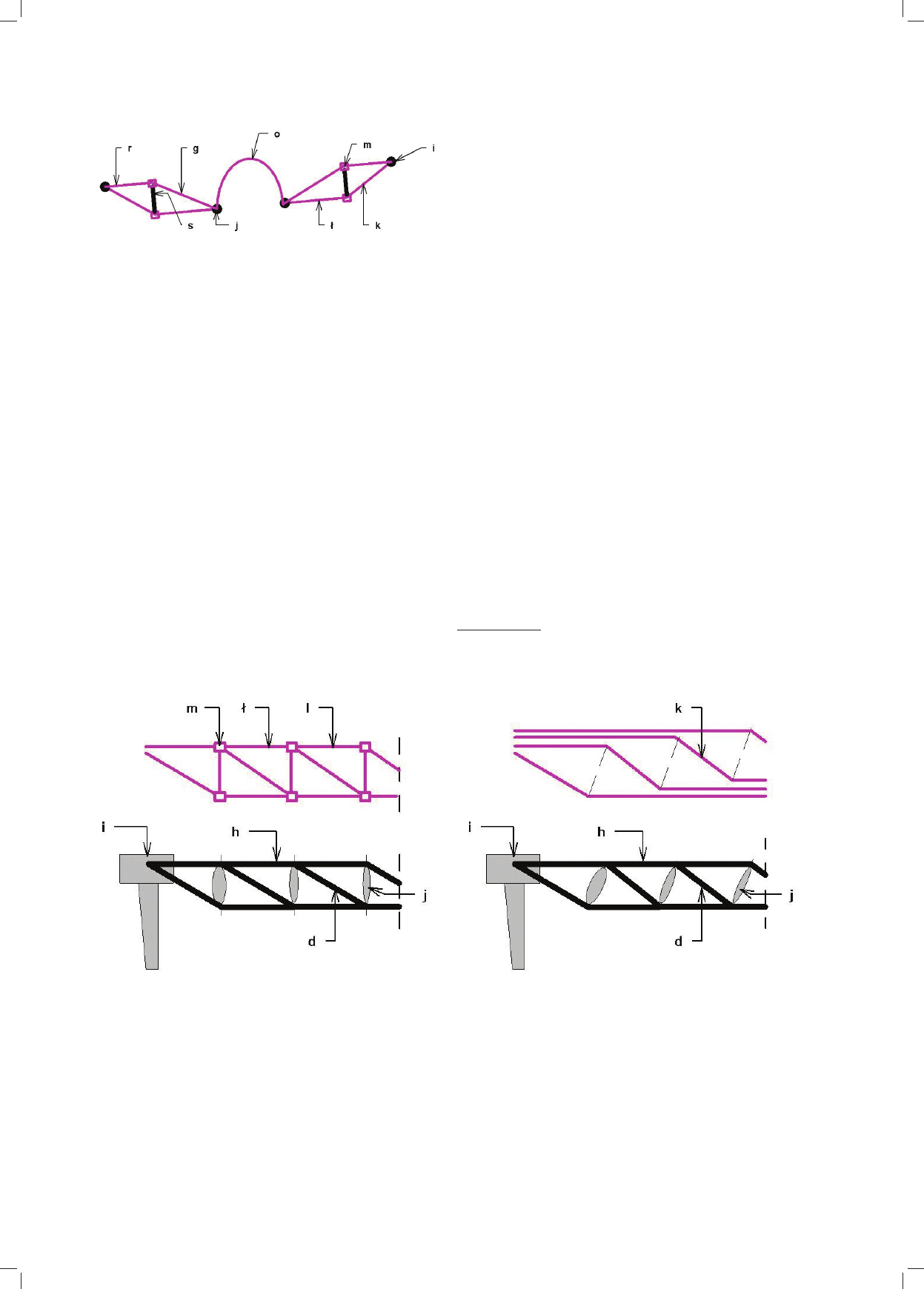
Il. 18. Schematy przedstawiają dwa typy dźwigarów prętowo-cięgnowych wykonanych z elementów krótkich łączonych w węzłach (lewy szkic)
oraz z elementów przebiegających swobodnie przez węzły (prawy szkic). Schemat lewy górny przedstawia schemat kratownicy
prętowo-cięgnowej zbudowanej z elementów „ł, l” łączonych w węzłach „m”. Siły w każdym elemencie są różne w zależności od miejsca
i obciążenia. Schemat lewy dolny to dźwigar płaski prętowo-cięgnowy tworzony na podstawie schematu górnego. Cięgna „h” kotwione są
w ściskanym pierścieniu zewnętrznym „i”. Krzyżulce „d” podwieszają węzeł dolny, a słupki „j” podpierają węzeł górny.
Schemat prawy górny przedstawia budowę dźwigara płaskiego prętowo-cięgnowego, w którym elementy linowe „k” przeciągane są w całości
od pierścienia wewnętrznego do pierścienia zewnętrznego (rys. autora)
Fig. 18. The diagrams show two types of cable-strut girders made from the members joined in the nodes (left sketch) and the members running
freely through the nodes (right sketch). The upper left sketch shows the diagram of a cable-strut built truss built from members “ł, l” joined in
nodes “m”. The forces in each member are different depending on load and location. The lower left sketch shows the flat cable-strut girder created
on the basis of the upper sketch. Cables “h” are anchored in external compression spring “i”. Cross braces “d” suspend the lower node,
and posts “j” support the upper node. The upper right sketch show the structure of flat cable-strut girder in which cable members “k” are pulled
in whole from the internal ring to the external ring (drawn by the author)
Il. 17. Schemat przedstawia uproszczony system płaskiej kratownicy
prętowo-cięgnowej bardzo zbliżonej do rozwiązania zastosowanego
w przekryciu hali Spodka. Docelowo elementy „r, g” i „ł, k” zostały
wykonane z wiązki pojedynczych lin, więc węzły „m” zostały ostatec-
znie pominięte. System tego typu polega na wzajemnym podwieszaniu
poprzez słupek „s” kolejnych układów podwieszających.
Na schemacie układ „ł, k” dźwiga układ „r, g”, który dźwiga kopułę.
Kable kotwione są w pierścieniu wewnętrznym „j” oraz w pierścieniu
zewnętrznym „i”. Kopuła pełni funkcję balastu utrzymującego odpow-
iedni naciąg systemu, który dzięki temu nie jest wra
żliwy na siły ssące
od wiatru. Przechylenie układu powoduje, że składowe poziome
obciążenia muszą być przejęte przez tarczę dachu i przeniesione
na konstrukcję wspierającą pierścień zewnętrzny dachu (rys. autora)
Fig. 17. The diagram shows the simplified system of a flat cable-strut
truss very similar to the solution applied to the Spodek hall cover.
Eventually, members “r, g” and “ł, k” were made from a bunch
of single
cables so nodes “m” were finally left out. The system
of this type is built by suspending one from another, through post “s”
of the successive suspending systems. In the diagram, system “ł, k”
bears system “r, g” which, in turn, bears the dome. The cables are
anchored in internal ring “j” and in external ring “i”. The dome plays
the role of ballast maintaining the proper tension of the system,
which thanks to this is not sensitive to suction forces from winds.
The inclination of the system causes the situation in which
the horizontal components of loads must be taken over
by the roof disc and transferred to the structure supporting
the external ring of the roof (drawn by the author)

O kształtowaniu konstrukcji dachu katowickiej hali Spodka /About shaping the structure of Katowice Spodek-arena roof 81
that: “When First Se cretary Władysław Gomułka learnt
about an extremely ex pensive investment under construc-
tion in Katowice, he issued a ban on constructing any-
thing else apart from in dustrial structures. However, the
construction process had not been discontinued because
upon the motion of Gen. Ziętek the construction site was
surrounded with a high fence and the drivers of the First
Sec retary were instructed to describe the construction site
as an industrial one.
The concept of Gen. Ziętek involved taking advantage
of any investment opportunities in order to create a sports
and cultural support base for large events, including the
Olympics in Upper Silesia which he dreamt about. There
were three arguments behind the plans of the Polish
endeavour for hosting the Olympics:
– Poland was considered as having a communist face
acceptable to the world, no other country in the bloc
enjoyed such autonomy as Poland did,
– Our contacts with the world of non-governmental
organisations were wide and one of the strongest in the
communist bloc,
– High organisational efficiency of Gen. Ziętek’s staff
along with mining and architectural organisations were
a gua rantee of success in that ambitious undertaking.
Gen. Ziętek ‘set himself as a matter of honour’ a goal
of urban transformation of the conurbation of central Si le-
sia cities later called Upper-Silesian Industrial Region
(Gór no śląski Okręg Przemysłowy) and especially the city
of Ka to wice which was then a clus ter of accidental de ve-
lop ment.
The new objects included the Voivodeship Park of
Culture and Recreation (in Polish: Wojewódzki Park
Kultury i Wypoczynku)
9
, the Silesian Stadium (Stadion
Śląski), the unique object of the Flower Hall and the
nearby Bail don Hall covered with a suspension roof
10
.
Also, the stadiums in Gliwice, Zabrze and in the neigh-
bourhood underwent expansion.
Eventually, in spite of such intensive development the
team of Gen. Ziętek was unable to complete the social
and municipal plan”
11
, nevertheless the valuable build-
ings still exist and most of them serve the inhabitants of
the agglomeration.
Unfortunately, in 2012 the unique Baildon Hall was
demolished according to a scenario similar to the Super-
sam building, but still there is consolation in knowing that
owing to proper inspection and maintenance the Spodek
hall is still in good shape and has become a well-known
symbol of Silesia.
Translated by
Bogusław Setkowicz
9
The park is located in the industrial areas on the boundary of the
cities Katowice, Chorzów and Siemianowice Śląskie and is one of the
largest urban parks worldwide.
10
Alfred Korpys was the author of the structure.
11
From the author’s interview with architect Prof. Henryk Buszko.
Przy zastosowaniu natomiast linowych elementów
ciągłych „k” (il. 18), przebiegających bez oporu przez
węz ły pośrednie „m”, konieczne staje się usytuowanie
słupków „j” rozpierających liny w dwusiecznej kąta mię-
dzy linami. Siła w linie dąży bowiem do wyrównania
swej wartości przed węzłem i za węzłami, więc naturalnie
słupek – dewiator „spychany” będzie w oś działania wy-
padkowej, tj. w pozycję równowagi.
Podsumowanie – tło historyczne
Rozważania przeprowadzone w artykule dotyczyły
głównie etapów kształtowania konstrukcji dachu hali
Spodka i nie poruszyły zagadnień nie mniej interesującego
systemu jej fundamentów. Nie ulega jednak wątpliwości,
że podobny obiekt nie powstał dotąd na świecie i forma
architektoniczna oraz wiele rozwiązań konstrukcyjnych
w nim zastosowanych są wyjątkowe w skali światowej.
Projekt konstrukcji Spodka bez cienia wątpliwości uznać
można za niezwykle śmiały jak na tamte czasy, ale co
ważniejsze – również na czasy dzisiejsze.
Hala powstawała blisko 10 lat w rzeczywistości racz-
kujących jeszcze komputerów i w trudnych warunkach
politycznego napięcia między władzą centralną a władza-
mi regionu Górnego Śląska. Nieocenione wsparcie dla
pod ważanej inwestycji zapewnił gen. Jerzy Ziętek, który
w latach 1964–1973 był przewodniczącym Prezydium
Wojewódzkiej Rady Narodowej w Katowicach
8
. Anegdo-
ta mówi, że: „Gdy I sekretarz Władysław Gomułka do-
wie dział się o budowie piekielnie drogiej inwestycji
w Kato wicach, wydał zakaz budowy czegokolwiek inne-
go niż obiektów przemysłowych. Budowa nie została
jednak przerwana, ponieważ na wniosek generała Ziętka
miejsce budowy osłonięto wysokim płotem, a kierowcy
transportu jący sekretarza byli pouczeni, by budowę
opisywać jako prze mysłową.
Koncepcja generała Ziętka polegała na wykorzysta niu
wszelkich możliwości inwestycyjnych do stworzenia
bazy zespołów sportu i usług kulturowych dla wielkich
imprez, w tym olimpiady sportowej na Śląsku, o której
marzył. Za planami ubiegania się Polski o organizację
olimpiady przemawiały trzy argumenty:
– Polska była traktowana jako dopuszczalne dla świata
oblicze komuny, żaden inny kraj bloku nie miał takiej
samodzielności jak Polska,
– nasze kontakty ze światem organizacji pozarządowych
były znaczne i jedne z silniejszych w bloku wschodnim,
– wysoka sprawność organizacyjna załogi gen. Ziętka
wraz z technicznymi organizacjami górniczymi oraz ar-
chitektonicznymi były gwarantem powodzenia ambitne-
go przedsięwzięcia.
Generał »postawił sobie za punkt honoru« upo rząd-
kowanie urbanistyczne konurbacji miast centrum Śląska
zwanego później Górnośląskim Okręgiem Przemysłowym,
a w szczególności miasta Katowice, które wówczas było
zlepkiem przypadkowej zabudowy.
8
http://pl.wikipedia.org/wiki/Jerzy_Zi%C4%99tek [data dostępu:
28.05.2013].

82 Michał Pelczarski
Powstał wówczas Wojewódzki Park Kultury i Wy po-
czyn ku
9
, Stadion Śląski, unikatowy obiekt Hali Kwiatów,
a w jego pobliżu Hala Baildonu przekryta dachem wiszą-
cym
10
. Rozbudowie uległy również stadiony w Gliwicach,
w Zabrzu i okolicy. Ostatecznie jednak, pomimo tak in-
tensywnego rozwoju, zespołowi gen. Ziętka nie udało się
9
Park zlokalizowany jest na terenach poprzemysłowych na gra-
nicy miast: Katowic, Chorzowa i Siemianowic Śląskich. To jeden z naj-
większych parków miejskich na świecie.
10
Autorem konstrukcji był inż. Alfred Korpys.
Streszczenie
Powyższy artykuł poświęcony jest rozważaniom na temat sposobów konstruowania ekonomicznych systemów stropowych i dachowych w oparciu
o analizę pracy kołowej płyty zginanej podpartej ciągle na obwodzie. Spektakularnym rezultatem takich rozważań jest pierwotna konstrukcja dachu
hali Spodka zaproponowana przez prof. Wacława Zalewskiego, która wniosła do zestawu rozwiązań dostępnych dla inżynierów i architektów pierw-
sze rozwiązanie z opatentowanej później rodziny typu tensegrity. W artykule przedstawiono również schematy ostatecznie zastosowanego roz wią-
zania konstrukcji dachu tego obiektu.
Słowa kluczowe: Spodek, tensegrity, praca płyty kołowej, momenty główne równoleżnikowe
Abstract
This article is about the methods of designing economic floor and roof structures based on the work of a circular bending plate, supported conti nually
at the edge. A spectacular result of such considerations was the first tensegrity system defined by Prof. Wacław Zalewski which contributed to the
set of solutions accessible to engineers and architects as the first solution of which later a patent was taken for the tensegrity type of group.
The article also shows the final solution of the roof structure of the Spodek hall.
Key words: Spodek, tensegrity, structural behaviour of circular slab, circumferential moments
Bibliografia /References
[1] Allen E., Zalewski W., Form and Forces, Designing efficient
expressive structures, John Wiley & Sons, Hoboken 2010.
[2] Dąbrowski O., Kolendowicz T., Poradnik inżyniera i technika bu-
dowlanego, t. 3, Arkady, Warszawa 1998.
[3] Informacje o warunkach geologiczno-górniczych, WUG, Katowice
2009.
[4]
Kączkowski Z., Płyty – obliczenia statyczne, Arkady, Warszawa 1968
.
[5] Kobiak J., Stachurski W., Konstrukcje żelbetowe, Arkady, Warsza-
wa 1960.
[6] Kuś S., Szybkie metody sprawdzania sił wewnętrznych w konstruk-
cjach, [w:] A. Richhart (red.), Nowe osiągnięcia nauki i techniki
w budownictwie, materiały konferencyjne, Rzeszów 2005, 135.
[7] Rękopisy Profesora Wacława Zalewskiego [w posiadaniu autora
artykułu].
[8] Starosolski W., Konstrukcje żelbetowe, t. 2, PWN, Warszawa 1998.
[9] Stiglat K., Wippel H., Platten, Wilhelm Ernst & Sohn, Berlin 1966.
[10] Zamorowski J., Specyfika konstrukcji Hali Widowiskowo-Spor-
towej – Spodek w Katowicach, Zeszyty Naukowe Politechniki
Rze szowskiej, Budownictwo i Inżynieria Środowiska, 2011, z. 58,
422–432.
[11] Żurawski A., Konstrukcja wojewódzkiej Hali Widowiskowo-Spor-
towej w Katowicach, praca doktorska, Warszawa 1977.
dopełnić planu socjalno-ko mu nalnego”
11
, mimo to cenne
obiekty pozostały i większość z nich od lat służy miesz-
kańcom aglomeracji.
Niestety w roku 2002 wyjątkowa Hala Baildonu zos tała
rozebrana według podobnego scenariusza co obiekt Super-
samu, ale pocieszające jest, że Spodek dzięki właś ciwemu
do zorowi i konserwacji nadal jest w dobrej kondycji i stał
się powszechnie znanym na świe cie symbolem Śląska.
11
Z wywiadu autora z prof. inż. arch. Henrykiem Buszko.