2015
1(41)
DOI: 10.5277/arc150108
Piotr Furmanek*
Fasady fraktalne
Fractal facades
Wprowadzenie
Fraktale
1
to obiekty geometryczne, które można zdefi -
niować trzema właściwościami:
– metoda generowania jest określona zależnością re-
kurencyjną,
– wymiar jest najczęściej liczbą ułamkową,
– cechą charakterystyczną jest samopodobieństwo.
Pierwsza cecha określa zależność kolejnego wyra zu
ciągu od wyrazu poprzedniego. Druga, dotycząca po ję -
cia wymiaru, ma szczególne znaczenie, ponieważ w od-
różnieniu od innych obiektów wymiar Hausdorffa w przy -
pad ku fraktali jest liczbą ułamkową. Ostatnia, trze cia
cecha samopodobieństwa w uproszczeniu oznacza, że
każda część fraktala jest pomniejszoną kopią całości [1,
s. 62].
Ze względu na sposób generowania obiekty fraktalne
moż na podzielić na cztery typy:
– fraktale klasyczne generowane za pomocą procedury
opisowej,
– fraktale generowane za pomoc
ą systemu funkcji ite-
rowanych (Iterated Function System – IFS),
– fraktale generowane za pomocą systemu Linden -
mayera (L-systemu),
– powierzchnie fraktalne.
* Wydział Architektury Politechniki Wrocławskiej/Faculty of
Archi tecture, Wrocław University of Technology.
1
Pojęcie „fraktal” wprowadzone przez Benoit Mandelbrota po -
chodzi od łacińskiego fractus – złamany, częściowy.
Fractal facades
Fractals
1
are geometrical objects which can be defined
by three properties:
– method of generation is determined by the recurrent
relationship,
– dimension is most often a fractional number,
– self-similarity is their characteristic feature.
The first feature determines the relationship between
the succeeding element of a sequence and the preceding
element. The second, regarding the notion of dimension,
has special significance as, unlike other objects, the Haus-
dorff dimension in the case of fractals is a fractional num-
ber. The last, third feature of self-similarity in simple
terms means that each part of a fractal is a downscaled
copy of the whole [1, p. 62].
Depending on their generation method, fractal objects
can be divided into four types:
– classic fractals generated with the use of descriptive
procedure,
– fractals generated with the use of IFS method (Ite-
rated Function System),
– fractals generated with the use of Lindenmayer sys-
tem (L-system),
– fractal surfaces.
1
The term “fractal” coined by Benoit Mandelbrot derives from
Latin fractus – fractured, partial.

98 Piotr Furmanek
Fasady fraktalne w budowlach historycznych
Od momentu stworzenia przez Benoit Mandelbrota
podstaw teorii fraktali badania w tym kierunku odbywały
się w wielu dziedzinach jednocześnie. Odkrycia do ty-
czą ce fraktalnej geometrii natury opublikowane przez
Mandelbrota w pracy The Fractal Geometry of Na ture
(Fra ktalna geometria natury) [2] zainspirowały nau-
kow ców wielu dziedzin do głębszej analizy przedmiotu
ich badań. Fala zainteresowań nie ominęła dziedzin zaj-
mu jących się teorią architektury. Wśród wielu tematów
dotyczących związków geometrii fraktalnej z architekturą
istotne miejsce zajmują prace dotyczące fasad o cha rak-
terze fraktalnym.
Carl Bovill, profesor Uniwersytetu w Maryland, w pra-
cy zatytułowanej The Doric Temple as a Fractal (Po rzą-
dek dorycki jako fraktal) [3] dokonuje analizy świątyni
grec kiej o porządku doryckim. Według niego w układzie
fa sa dy można zauważyć elementy związane cechą sa-
mo podobieństwa, najbardziej charakterystyczną cechą
obiek tów fraktalnych. Swoją tezę próbuje udowodnić,
wy korzystując jedną z najbardziej rozpowszechnionych
me tod generowania fraktali – system funkcji iterowanych,
zwa ny w skrócie IFS. Podstawą tej metody jest prze kształ-
canie obiektów geometrycznych za pomocą transformacji
afi nicznych, a następnie wielokrotne powtarzanie tej
samej operacji na kolejno uzyskiwanych zbiorach.
Według Bovilla poddanie układu kolumn z architrawem
operacji skalowania o odpowiednio dobranych parame-
trach prowadzi do uzyskania rysunku żłobkowanej ko-
lumny wraz z wieńczącą głowicą. Dowodem może być
zgodność liczby kaneli z liczbą kolumn podpierających
architraw w klasycznej świątyni doryckiej. Jeżeli liczba
kaneli wynosiła 16–20, to na widocznej ortogonalnie części
kolumny występowało 8–10 krawędzi oddzielających
kanele. W przypadku ośmiu krawędzi liczba ta jest zgodna
z liczbą ośmiu kolumn frontonu Partenonu – kanonicznej
świątyni doryckiej.
W dalszej analizie Carl Bovill odkrywa cechę samo-
podobieństwa pomiędzy układem frontonu a kompozycją
tryglifu. Dowodem jest przekształcanie skalowania ze
specjalnie dobranymi parametrami odręcznych rysunków
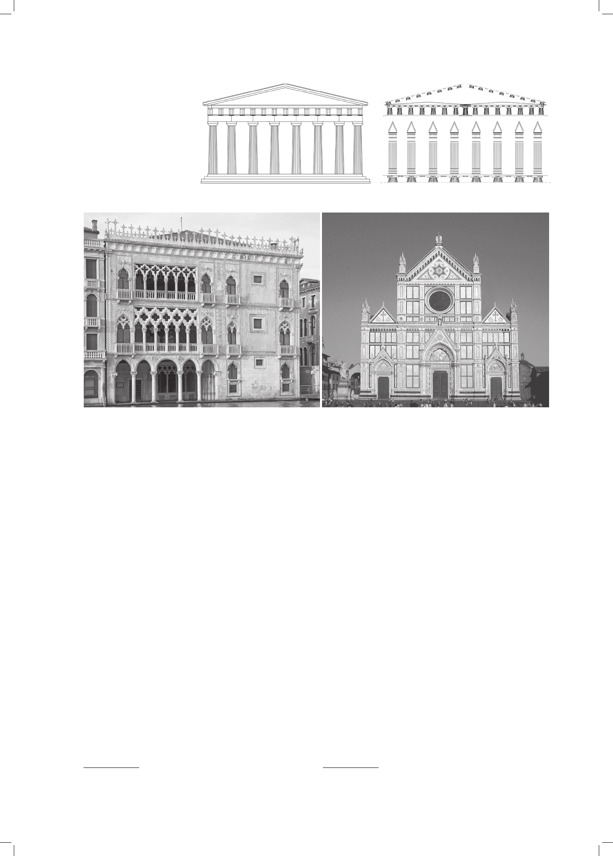
frontonu świątyni (il. 1). Zgodnie z rekurencyjnie stoso-
wa ną metodą IFS następne przekształcenia skalowania
tryglifów prowadzą do uzyskania elementów zwanych
mutulae
2
i guttae
3
. Według Bovilla samopodobieństwo or-
namentów frontonu ma czterostopniową głębię
4
, co mo-
że być dowodem na fraktalny charakter fasady świą tyni
doryckiej.
Wątpliwości może budzić odręczny charakter ry sun-
ków fasad badanych budowli oraz wybiórcza akceptacja
wyników przekształceń IFS, w których wyniku w uzy ska-
nym obrazie kolumny będącej zredukowanym obrazem
2
Mutulae (łac. mutulus) – prostokątna płytka mocowana do spod-
niej powierzchni gzymsu.
3
Guttae (łac. – łezki, krople) – rodzaj ornamentu umieszczany pod
mutulusem lub na spodniej części gzymsu.
4
Oryg.: The IFS analysis of a Doric temple clearly shows a self-
affine cascade of ornament that is four levels deep [3, s. 288].
Fractal facades in historical buildings
Since the moment when the basis of the theory of frac-
tals was developed by Benoit Mandelbrot research in this
area has been conducted in numerous fields at the same
time. Discoveries regarding fractal geometry of the nature
published by Mandelbrot in The Fractal Geometry of
Nature [2] inspired scientists in many fields to analyze the
object of their research deeper. A wave of interest was
also evident in the areas regarding the theory of architec-
ture. Many topics regarding the relationships between the
geometry of fractals and architecture included works
regarding fractal facades.
Carl Bovill, professor at the University of Maryland, in
his work The Doric Temple as a Fractal [3] analyzes the
Greek temple built in the Doric order. In his opinion its
facade, demonstrates some elements connected with self-
similarity, the most characteristic feature of fractal objects.
He tries to prove his claim with the use of one of the most
popular fractal generation methods – IFS. The basic con-
cept in this method is to transform geometrical objects
with the use of affine transformations and then repeat the
same operation multiple times with the next sets.
According to Bovill subjecting a system of columns
with the architrave to scaling with adequately selected
parameters results in a drawing of a fluted column crow-
ned with a ca pital. Proof can be provided by the consis-
tency of the num ber of flutes with the number of co lumns
supporting the architrave in the classic Doric tem ple. If
the number of flutes was 16–20, then the orto gonally vi -
sible part of the column had 8–10 edges separating the
flutes. In the case of eight edges, this number is consistent
with the number of eight columns of the front of the
Parthenon – the canonic Doric temple.
Further in his analysis, Carl Bovill discovers the fea-
ture of self-similarity between the front and the composi-
tion of the triglyph. Proof comes from the transformation
of scaling with specially selected parameters of hand-made
drawing of the front of the temple (Fig. 1). Accord ing to
the recurrently applied IFS method the successive trans-
formations of scaling triglyphs result in the elements
called mutulae
2
and guttae
3
. According to Bovill self-
simi larity of ornaments of the front has four levels of
depth
4
which can prove the fractal nature of the facade of
this Doric temple.
Some doubt may arise from the sketchy nature of the
drawings of the facades of the buildings being studied as
well as a selective acceptance of the results of IFS trans for-
ma tions which resulted in an image of a column, being a re -
duced
image of the facade, with a scaled triangle as a nar-
rowed image of the tympanum in the place of its capital.
Nicoletta Sala, professor at the University of Mendrisio,
University of Italian Switzerland, Lugano, in the article
2
Mutulae (Latin mutulus) – rectangular projecting shelf under
the corona of a cornice.
3
Guttae (Latin – drops) – a kind of ornament placed under the
mutulus or on the underside of the cornice.
4
Orig.: The IFS analysis of a Doric temple clearly shows a self-
affine cascade of ornament that is four levels deep [3, p. 288].
Fasady fraktalne / Fractal facades 99
fasady w miejscu głowicy pojawia się przeskalowany
trójkąt jako zwężony obraz tympanonu.
Nicoletta Sala, profesor Uniwersytetu w Mendrisio, Uni -
versity
of Italian Switzerland, Lugano, w artykule Frac-
tal components in the Gothic and in the Baroque Ar-
chitecture (Fraktalne elementy w architekturze gotyckiej
i ba rokowej) [4] doszukuje się cech samopodobieństwa
w fasadach gotyckich katedr. Jako przykład podaje ka-
tedrę w Reims, wskazując elementy ostrołukowe portali
i zwień czeń otworów okiennych w wyższych partiach
ele wacji. Różne gabaryty elementów według Sali są
wynikiem przekształceń portalu głównego w systemie
IFS. Również we wnętrzu katedry gotyckiej występujące
elementy ostrołukowe mają świadczyć o fraktalnym cha-
rakterze budowli.
Innym przykładem występowania fraktalnych cech
w architekturze gotyku według Nicoletty Sali może być
fasada Ca’ d’Oro
5
– pałacu w Wenecji, położonego nad
Canal Grande w dzielnicy Canareggio (il. 2). Fasada tej
budowli charakteryzuje się asymetryczną kompozycją.
5
Ca’ d’Oro – Złoty Dom, nazwa pochodzi od faktu iż pierwotnie
znaczne części elewacji pokryte były złotem.
Fra ctal components in the Gothic and in the Baroque Ar -
chitecture [4] sees self-similarity features in the facades
of Gothic cathedrals. As an example he uses the cathedral
in Reims, indicating the elements with pointed arches
of the portals and window openings in the upper sections
of the facade. Different dimensions of the elements result,
in his opinion, from the transformations of the main portal
in the IFS system. The Gothic cathe dral also has some
elements with pointed arches inside which are supposed
to testify to the fractal nature of the building.
According to Nicoletta Sala the facade of Ca’ d’Oro
5
– the palace in Venice, located by the Grand Canal in the
district of Canareggio – can be another example of fractal
features in Gothic architecture (Fig. 2). It has a character-
istic asymmetric composition. Its left part has a portico
with two rows of storeys with elements of a loggia above
it, and a blind arcade below the cornice. Most of its right
part is a plain wall. The portico, the loggias, and the ele-
ments of a frieze have arches of different sizes but their
shapes are similar (Fig. 2). Accepting this fact as a self-
5
Ca’ d’Oro – Golden House; its name derives from the fact that
originally large sections of its facade were gilded.
Il. 2. Elewacje frontowe pałacu Ca’ d’Oro w Wenecji (źródło: http://pl.wikipedia.org/wiki/Plik:Ca%27_d%27Oro_facciata.jpg;
autor: Didier Descouens [praca własna] [CC BY-SA 4.0])
i kościoła Świętego Krzyża we Florencji (źródło: http://pl.wikipedia.org/wiki/Plik:Santa_croce_facciata.JPG; autor: Sailko [CC BY 3.0])
Fig. 2. Front facades of Ca’ d’Oro palace in Venice (source: http://pl.wikipedia.org/wiki/Plik:Ca%27_d%27Oro_facciata.jpg;
author: Didier Descouens [own work] [CC BY-SA 4.0])
and the Basilica of the Holy Cross in Florence (source: http://pl.wikipedia.org/wiki/Plik:Santa_croce_facciata.JPG; autor: Sailko [CC BY 3.0])
Il. 1. Fasada zachodnia Partenonu
j
ako fraktal generowany
metodą IFS (rys. autora
wykonany na podstawie
rysunków Carla Bovilla [3])
Fig. 1. West facade of
the Parthenon as a fractal
generated by IFS (drawing by
the author on the basis of
Carl Bovill’s drawings [3])

100 Piotr Furmanek
W lewej części występuje portyk, nad którym usytuowane
są dwie kondygnacje z elementami loggii, a poniżej
gzymsu fryz arkadkowy. W prawej części przeważa lita
ściana. Portyk, loggie oraz elementy fryzu zwieńczone są
łukami o różnych gabarytach, ale podobnych kształtach
(il. 2). Uznając ten fakt za cechę samopodobieństwa, Ni-
co letta Sala sformułowała twierdzenie o fraktalnym cha -
rakterze fasady pałacu Ca’ d’Oro.
Wątpliwości może budzić niezgodność kształtów ostro-
łuku portyku i łukowego okrągłego fryzu arkadkowego.
Trudno też stwierdzić zależność liczbową (skalę po do -
bieństwa) między gabarytami elementów o różnych wiel-
kościach.
Jako kolejny przykład elewacji, w której występują
ele menty samopodobne, Nicoletta Sala prezentuje fronton
koś cioła Świętego Krzyża we Florencji (Santa Croce) po-
cho dzącego z przełomu XIV i XV w. (il. 2). Według Sali
samopodobieństwo występuje mię dzy układem trzech
fron tonów usytuowanych nad wejś cio wymi portykami
a układem trzech tympanonów wień czących fasadę.
Fasady fraktalne w budowlach współczesnych
Badania nad fraktalnym charakterem fasad we współ-
czesnej architekturze kontynuuje Carl Bovill. W dziele
za tytułowanym Fractal Geometry in Architecture and
De sign między innymi zajmuje się pojęciem wymiaru
frak tal ne go. W obszernym wprowadzeniu omawia zasady
po mia ru fraktalnego opartego na wymiarze powszechnie
na zy wa nym wymiarem pudełkowym (box counting di-
mension).
Zasada pomiaru pudełkowego polega na pokryciu da -
nego obiektu płaszczyznowego siatką kwadratów
6
, a na -
stęp nie zliczeniu, w ilu kwadratach pojawia się frag ment
obiektu. Liczba N kwadratów zależy od parametru dłu-
gości boku kwadratu a. Zmniejszanie parametru dłu goś ci
boku powoduje zwiększenie liczby kwadratów, a jed no-
cześnie zwiększenie dokładności pomiaru. Wynik po mia ru
pudełkowego d jest ilorazem logarytmu liczby kwa dra tów
potrzebnych do pokrycia obiektu i logarytmu odwrotnoś-
ci parametru długości boku kwadratu
7
[1, s. 195]:
d =
Iloraz różnic wartości uzyskanych w dwóch kolejnych
pomiarach stanowi wymiar fraktalny D [1, s. 203], [5,
s. 119–121]:
D =
Topologiczny wymiar obiektów płaszczyznowych
wynosi 2, a obiektów przestrzennych 3. Wymiar frak-
tal ny kwadratu wynosi również 2, a sześcianu analo-
gicznie 3, ale w przypadku fraktali, których struktura
6
W przypadku obiektu przestrzennego siatką sześcianów – stąd
nazwa box counting dimension.
7
Dokładniej: 1/a jest współczynnikiem skali podobieństwa wiel-
kości boku kwadratu na danym etapie pomiaru w stosunku do pomiaru
pierwszego – wielkości kwadratu, w którym mieści się cały obiekt.
similarity feature, Nicoletta Sala formulated the claim
that the facade of Ca’ d’Oro palace is fractal in its nature.
Some doubts can arise from the inconsistency of the
shapes of pointed arches in the portico and round arches
of the blind arcade. It is also difficult to establish the
numerical relationship (similarity scale) between the di -
men sions of the elements of various sizes.
As an another example of a facade with self-similiar
elements, Nicoletta Sala presents the front of the Holy
Cross in Florence (Santa Croce) from the turn of the 14
th
and 15
th
centuries (Fig. 2). According to Sala self-similar-
ity is present between the layout of three fronts located
above entrance porticos and the layout of three tympa-
nums crowning the facade.
Fractal facades in contemporary structures
Research on the fractal nature of facades in contempo-
rary architecture is continued by Carl Bovill. In his work
titled Fractal Geometry in Architecture and Design he
deals among other things with the notion of fractal dimen-
sion. In a long introduction he describes the principles of
fractal counting based on the dimension which is univer-
sally known as box counting dimension.
The box counting principle consists in covering a given
flat object with a network of squares
6
and then counting
in how many squares a fragment of an object appears. The
number of squares N depends on the side length para-
meter of the square a. Decreasing the side length para-
meter results in increasing the number of squares and at
the same time increasing the counting precision. The
result of box counting d is the quotient of the logarithm of
the box counting needed to cover an object and the loga-
rithm of the opposite of square side length parameter
7
[1,
p. 195]:
d =
The quotient of the differences of the values which
result from two successive countings is the fractal dimen-
sion D [1, p. 203], [5, pp. 119–121]:
D =
The topological dimension of flat objects is 2, and of
spatial objects 3. The fractal dimension of the square is
also 2, and of a cube by analogy 3, but in the case of frac-
tals whose structure is complex and self-similar, the frac-
tal dimension is a fractional number.
Carl Bovill studied the facades of buildings designed
by Frank Lloyd Wright: Robie House and Unity Temple.
In the case of Robie House the facade was covered suc-
cessively with four networks, and the results of fractal
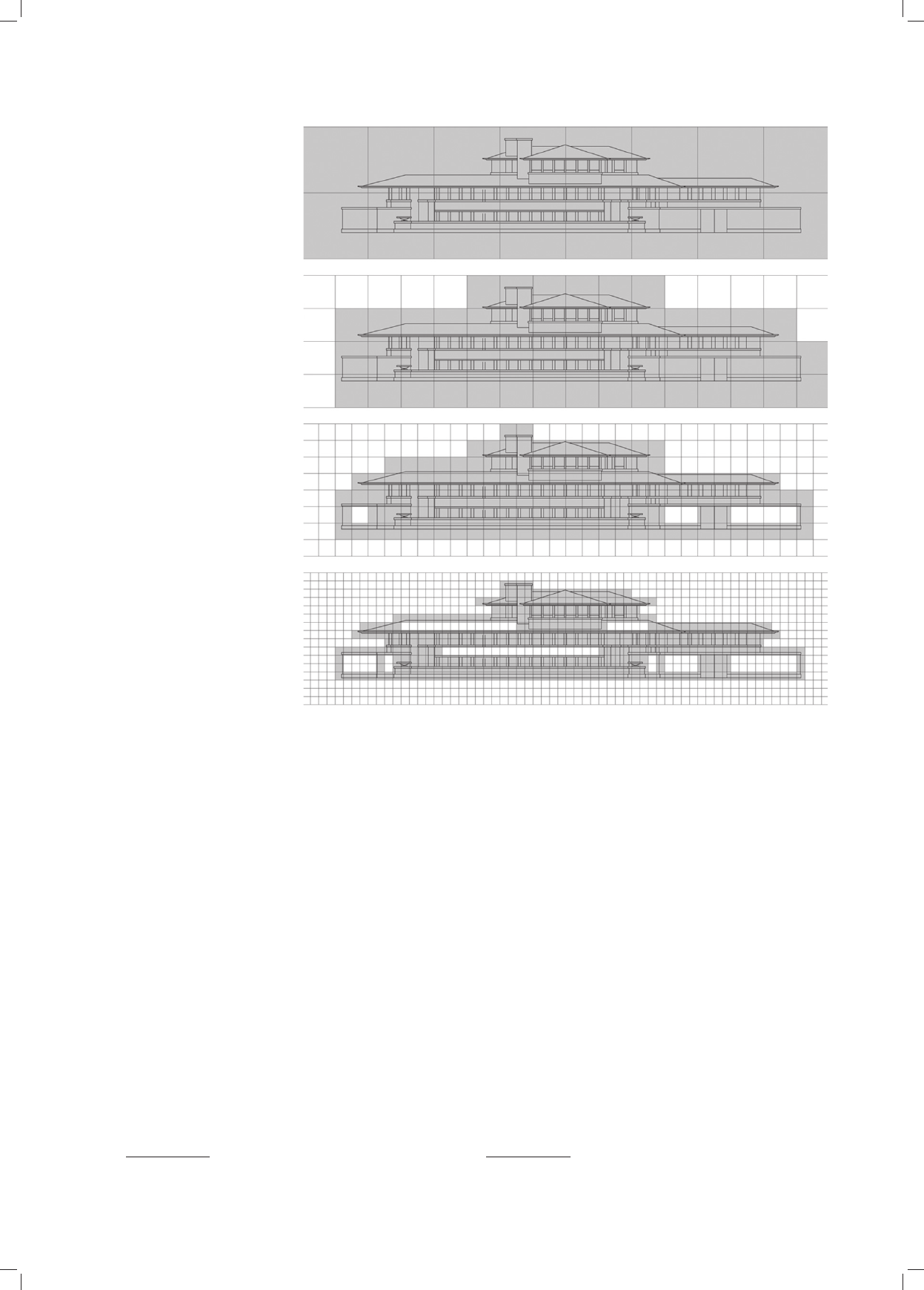
counting fell between d = 1.645 and d = 1.441 (Fig. 3). In
6
In the case of a spatial object with a network of cubes – thus the
name box counting dimension.
7
To be more precise: 1/a is the size similarity scale rate of the
square side in a given stage of counting in relationship to the first count-
ing – square size where the whole object fits.
log N
log 1/a
log N
1
– log N
2
log 1/a
1
– log 1/a
2
log N
log 1/a
log N
1
– log N
2
log 1/a
1
– log 1/a
2
Fasady fraktalne / Fractal facades 101
jest złożo na i samopodobna, wymiar fraktalny jest liczbą
ułamkową.
Carl Bovill poddał badaniom elewacje budynków
zaprojektowanych przez Franka Lloyda Wrighta: Robie
House i Unity Temple. W przypadku Robie House ele-
wacja została pokryta kolejno czterema siatkami, a wyni-
ki pomiaru fraktalnego wahały się pomiędzy d = 1,645
a d = 1,441 (il. 3). W przypadku Unity Temple wymiar
wynosił od d = 1,482 do d = 1,621.
Carl Bovill odżegnuje się jednak od jednoznacz nych
stwierdzeń, zaznaczając, że budynki nie są fraktalami
w taki sam sposób jak konstrukcje matematyczne, takie
jak krzywa van Kocha
8
. Porównuje proces pomiaru
fraktalnego, w którym dokonuje się kolejnych przybliżeń
z większą dokładnością, do percepcji wizualnej obiektu
architektonicznego: w miarę zbliżania się do budowli
zauważa się coraz więcej szczegółów na elewacji aż do
wejścia do wnętrza, w którym można zauważyć detale
okien czy drzwi. Na poparcie wywodu Bovill dokonuje
pomiaru fraktalnego detalu okna, w którym doszukuje się
8
Oryg.: Buildings are not fractals in the same way that mathe-
matical constructs such as the Koch curve are fractals [5, s. 117].
the case of Unity Temple the dimension was between d =
1.482 and d = 1.621.
Although Carl Bovill avoids definitive claims, noting
that the buildings are not fractals in the same way as
mathematical structures such as the Koch curve
8
. He com-
pares the process of fractal counting, with successive,
more and more accurate approximations, to the visual
perception of an architectural object: the closer you get to
a structure, the more and more details you notice on the
facade until you go inside, where you can see details
of windows and doors. In order to prove his point Bo vill
executes the fractal counting of the window detail, where
he claims to see some motifs of the Sierpinski triangle
– one of the most famous fractals. The fractal dimension
in this case was between d = 1.721 and d = 1.626 [5,
pp. 119–126].
In spite of the ambiguity of the claim regarding the
fractal nature of the architecture by Frank Lloyd Wright,
many researchers of fractal components in architecture
followed Bovill, applying the dimensional criterion as
8
Orig.: Buildings are not fractals in the same way that mathemat-
ical constructs such as the Koch curve are fractals [5, p. 117].
Il. 3. Pomiar fraktalny elewacji
południowej Robie House
(rys. autora wykonany
na podstawie rysunków
Carla Bovilla [5, s. 120, 122])
Fig. 3. Fractal measurement of
south facade of the Robie House
(drawing by the author on the
basis of Carl Bovill’s drawings
[5, p. 120, 122])
102 Piotr Furmanek
motywów trójkąta Sierpińskiego – jednego z najbardziej
znanych fraktali. Wymiar fraktalny w tym wypadku wahał
się od d = 1,721 do d = 1,626 [5, s. 119–126].
Pomimo niejednoznaczności wypowiedzi odnośnie
do fraktalnego charakteru architektury Franka Lloyda
Wrighta w ślad za Bovillem podążyło wielu badaczy kom -
ponentów fraktalnych w architekturze, stosujących kry -
terium wymiaru jako cechy pozwalającej na zaliczenie
da nego obiektu do budynków fraktalnych
9
.
Niezależnie od słuszności tez stawianych przez wspo -
mnianych naukowców wątpliwości budzi fakt ana li zo wa-
nia
płaskiego rysunku, który jest zaledwie ortogo nalną pro-
jekcją przestrzeni trzywymiarowej, a także przy jęcia jako
jedynego kryterium wymiaru fraktalnego z po mi nięciem
innych cech charakterystycznych obiektów fra ktalnych.
Kolejnym badaczem fasad fraktalnych jest Charles
Jencks, amerykański architekt i historyk architektury, autor
dzieła zatytułowanego The New Paradigm in Architec ture
z podtytułem The Language of Post-Modern Architec-
ture (Nowy paradygmat architektury – Język architektury
postmodernistycznej) [6]. W rozdziale The New Para-
digm II – Fractal Architecture (Nowy paradygmat II
– Architektura fraktalna) ogłasza narodziny nowego
kierunku architektury, przytaczając przykłady budowli na
poparcie swojej tezy.
Jednym z przykładów jest Federation Square – obiekt
zaprojektowany przez Petera Dawsona i Donalda L. Bate
-
sa z biura projektowego LAB Architecture Studio. Ele-
wacje budynku Federation Square zaprojektowano z wy-
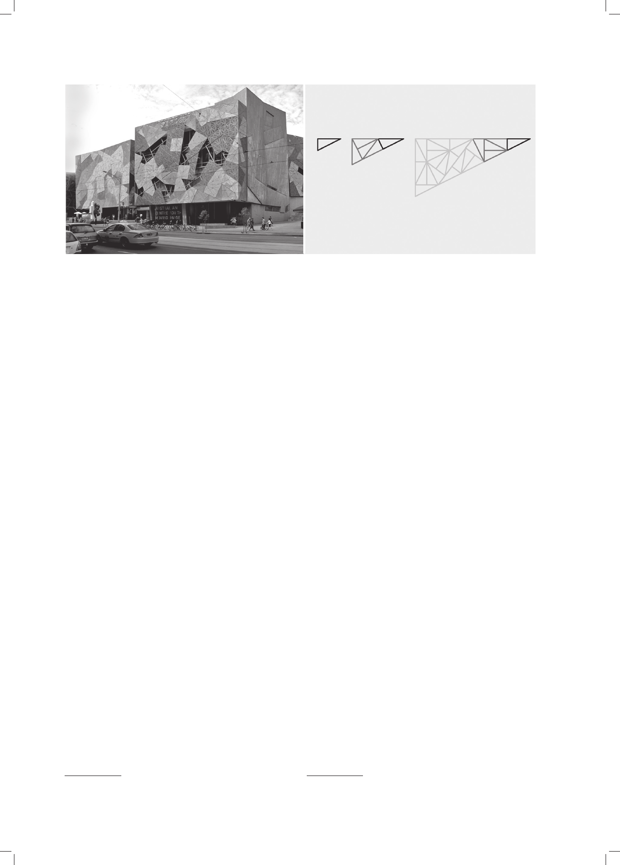
korzystaniem piaskowca, blachy cynkowej i szkła (il. 4).
Podziały elewacji oparte są na parkietażu nieokreso-
wym Johna Conwaya i Charlesa Radina. Podstawą kon -
strukcji tej teselacji jest przekształcanie trójkąta pro sto-
kątnego układem transformacji afi nicznych w ok reś lonym
porządku.
9
Jala Makhzoumi, Gloria Pungetti, Gerardo Burkle-Elizondo,
Nicoletta Sala, Ricardo David Valdez-Cepeda.
a feature on the basis of which a given object can be
included in the category of fractal buildings
9
.
Regardless of whether the theses put forward by the
above-mentioned scientists are correct or not, some
doubts arise from the fact of analyzing a flat drawing
which is just an orthogonal projection of a three-dimen-
sional space as well as assuming the fractal dimension as
the only criterion, disregarding other features characteris-
tic of fractal objects.
The American architect and historian of architecture,
Charles Jencks, the author of The New Paradigm in
Ar chi tecture subtitled The Language of Post-Modern Ar -
chitecture [6] is another researcher of fractal facades. In
the chapter titled The New Paradigm II – Fractal Ar -
chitec ture he proclaims the birth of a new direction in
architec ture, giving examples of structures to support his
claim.
One of the examples is Federation Square – designed
by Peter Dawson and Donald L. Bates from LAB Ar -
chitecture Studio. The facades of the Federation Square
building were designed with the use of sandstone, zinc
sheet, and glass (Fig. 4).
The divisions of the facade are based on non-periodic
tilings defined by John Conway and Charles Radin. The
structure of that tesselation is based on transforming
a right-angled triangle with affine transformations in a set
sequence.
The transformations of a triangle (translation, symme-
try, rotation) result in a panel composed of five copies of
the triangle. The panel and the triangle remain self-simi lar
(the triangle is a reduced copy of the panel). The transfor-
mation of the panel with a set of the same transformations
gives a megapanel which remains self-similar to both the
pa nel and the triangle (Fig. 4) [7, pp. 44–48]. This way
the fa cade of Federation Square, which demonstrates self-
9
Jala Makhzoumi, Gloria Pungetti, Gerardo Burkle-Elizondo,
Nicoletta Sala, Ricardo David Valdez-Cepeda.
Il. 4. Budynek Federation Square i schemat teselacji Conwaya/Radina (autor: Bidgee [praca własna], http://commons.wikimedia.org/wiki/
File:Australian_Centre_for_the_Moving_Image.jpg?uselang=pl, [CC BY 3.0], schemat teselacji – rysunek własny autora)
Fig. 4. Federation Square building and Conway/Radin tessellation (author: Bidgee [own work], http://commons.wikimedia.org/wiki/
File:Australian_Centre_for_the_Moving_Image.jpg?uselang=pl, [CC BY 3.0], schema tesselation – drawing by the author)
Fasady fraktalne / Fractal facades 103
Przekształcenia trójkąta (przesunięcie, symetria, ob-
rót) prowadzą do powstania panelu składającego się
z pię ciu kopii trójkąta. Panel i trójkąt pozostają w relacji
samopodobieństwa (trójkąt jest pomniejszoną kopią pa-
nelu). Przekształcanie panelu układem tych samych
przekształceń prowadzi do powstania megapanelu, który
pozostaje w relacji samopodobieństwa zarówno w sto-
sunku do panelu, jak i trójkąta (il. 4) [7, s. 44–48]. W ten
sposób elewacja Federation Square charakteryzuje się
cechą samopodobieństwa pozwalającą zaliczyć ją do fa-
sad o charakterze fraktalnym.
Analiza przedstawionych przykładów pozwala na
wyciągnięcie wniosków, iż we wszystkich przypadkach
fasady są traktowane przez badaczy tematu jako płaskie
rysunki elewacyjne, podczas gdy prawie zawsze fasada
jest w sensie geometrycznym obiektem trójwymiarowym,
reliefem.
Odmienną propozycją potraktowania fasady jako re-
lie fu o cechach fraktalnych może być wykorzystanie po -
wierzchni fraktalnej – jednego z typów obiektów frak-
talnych – jako elementu kształtującego formę elewacji.
Powierzchnie fraktalne
Wyróżnia się dwie podstawowe metody generowania
powierzchni fraktalnych zależne od sposobu teselacji
płaszczyzny:
– diamentowego kwadratu
10
opartą na teselacji kwa-
dratowej,
– triangulacyjną opartą na teselacji trójkątnej.
Obie metody działają w oparciu o ten sam algorytm
nazywany metodą losowego przemieszczenia punktu
środkowego (ang. random midpoint displacement method)
stosowaną między innymi w symulacji ruchów Browna
[1, s. 453]. Na potrzeby niniejszej pracy wyeliminowano
element losowości w doborze parametru przemieszczenia
punktu środkowego, zatem metodę diamentowego kwa-
dratu z predefi niowanym doborem parametrów translacji
można wyjaśnić w sposób następujący:
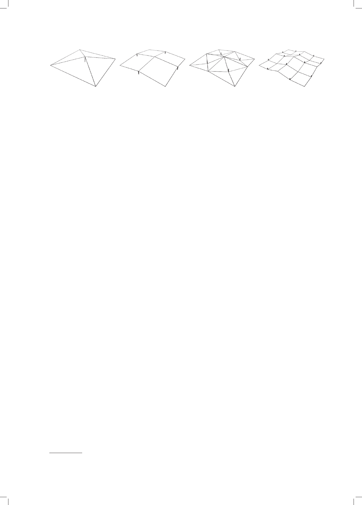
Obiektem początkowym jest kwadrat o boku a.
W pierw szym kroku konstrukcji punkt środkowy kwa -
dra tu zostaje przemieszczony na kierunku k pro sto pad-
łym do płaszczyzny kwadratu o parametr D
1,1
= a/8.
Zwrot wektora translacji dodatni. W kroku drugim prze-
10
Ang. diamond square method – brak ustalonego, formalnego
odpowiednika w języku polskim.
si mi larity features, can be considered to be a fractal
facade.
The analysis of the examples presented above leads to
the conclusion that all of these facades are considered by
the researchers to be flat facade drawings, whereas, geo-
metrically speaking, the facade is almost always a three-
dimensional object – a relief.
The use of a fractal surface – one type of fractal objects
– as an element shaping the facade form can be consid-
ered to be a different approach to the facade – a relief with
fractal features.
Fractal surfaces
There are two basic methods of generating fractal sur-
faces, depending on surface tesselation:
– diamond square based on square tesselation,
– triangulation based on triangular tesselation.
Both methods operate on the basis of the same algo-
rithm called the random midpoint displacement method
used for instance in simulation the Brownian motion [1,
p. 453]. For the purposes of this paper the element of
randomness in the selection of the midpoint displacement
parameter has been excluded, and so the diamond square
method with predefined selection of translation parame-
ters can be explained in the following way:
The initial object is a square with its side a. In the first
step of the construction the midpoint of the square is dis-
placed in the direction k perpendicular to the plane of the
square by parameter D
1,1
=
a/8. The sense of translation
vector positive. In the second step the midpoints of the
sides of the square are displaced by parameter D
1,2
=
D
1,1
/2 =
a/16. The sense of translation vector positive.
The displacement of the above-mentioned points gives an
object which is a set of four adjacent rhombuses with
sides b
=
a√5/4.
In the second step the procedure is repeated for the
rhombuses created in the first step. The midpoints of the
rhombuses are displaced in the direction k set in the first
step by parameter D
2,1
=
D
1,1
–
D
1,1
/8. The sense of trans-
lation vector negative. The midpoints of the sides of the
rhombuses are displaced in the direction k by parameter
D
2,2
=
D
2,1
/2. The sense of translation vector negative. In
the next steps the procedure is repeated for next rhom-
buses, the midpoint displacement parameters are reduced
in compliance with the decreasing constant amplitude
A =
D
1,1
= a/8, displacement direction k constant, the sen ses
of translation vector alternate for the successive construc-
Il. 5. Kolejne kroki konstrukcji powierzchni fraktalnej generowanej metodą diamentowego kwadratu
z predefiniowanym doborem parametrów przesunięcia punktu środkowego (źródło: rysunek własny autora)
Fig. 5. Next steps in the construction of the fractal surface generated with the diamond square method
with predefined selection of parameters of the midpoint displacement (source: drawing by the author)
104 Piotr Furmanek
mieszczeniu zostają poddane punkty środkowe boków
kwa dratu o parametr D
1,2
=
D
1,1
/
2 =
a/16. Zwrot wektora
translacji dodatni. W wyniku przemieszczenia wyżej
wy mienionych punktów powstaje obiekt będący ukła-
dem czterech przystających rombów o bokach b
=
a√5/4.
W kroku drugim procedura zostaje powtórzona dla
uzyskanych w kroku pierwszym rombów. Środkowe rom -
bów zostają przemieszczone na ustalonym w kroku pierw -
szym kierunku k o parametr
D
2,1
= D
1,1
– D
1,1
/8.
Zwrot wek -
tora translacji ujemny. Środkowe boków rombów zostają
prze mieszczone na kierunku k o pa ra metr
D
2,2
= D
2,1
/2.
Zwrot
wektora translacji ujemny. W na stęp nych krokach
procedura jest powtarzana dla ko lej nych rom bów, pa-
rametry przemieszczenia punktu środ kowe go redukowane
są zgodnie ze zmniejszającą się stałą am plitu dą wy no-
szącą A = D
1,1
= a/8, kierunek k prze miesz czenia stały,
zwroty wektora translacji prze mien ne dla kolej nych
wy stępujących po sobie kroków kon strukcji. Parame-
try przemieszenia środkowych bo ków zredukowane są
w stosunku do parametrów prze mieszczenia punktów
środ kowych o współczynnik redukcji r = 1/2. Kierunek
i zwrot jak dla punktów środ kowych (il. 5).
Powtórzenie procedury prowadzi do wykształcenia
po wierzchni wielościennej, która dąży do powierzchni
gład kiej. Pod względem cech fraktalnych można stwier-
dzić, że zgodnie z etymologią pojęcia fractal uzyskany
obiekt w pierwszych krokach konstrukcji charakteryzuje
się pofałdowaną, można powiedzieć „połamaną” – frak -
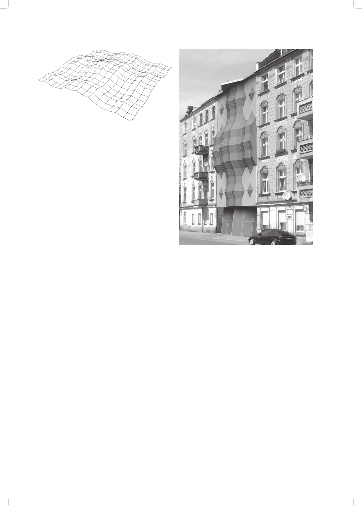
talną strukturą (il. 6). Predefi niowany dobór parametrów
prze mieszczenia punktu środkowego i rekurencyjne sto-
so wanie algorytmu zapewnia cechę samopodobieństwa –
najbardziej charakterystyczną cechę obiektów fraktalnych.
Podsumowanie: powierzchnia fraktalna
jako element fasady budynku
Uzyskana powierzchnia może być alternatywnym spo -
sobem kształtowania fasad o charakterze fraktalnym. Na
ilustracji 7 przedstawiono teoretyczny przykład wy ko-
rzystania powierzchni fraktalnej (czwarty krok konstruk -
cji) jako elementu przeszklenia fasady budynku w zabu do-
wie uzu pełniającej na terenie obszaru zurbanizowanego.
Wy ko rzystanie powierzchni o predefi niowanych para-
tion steps. The side midpoint displacement parameters
are reduced in relationship to the midpoint displacement
parameters by reduction rate r
=
1/2. The direction and the
sense the same as for midpoints (Fig. 5).
The repetition of the procedure finally creates a poly-
hedral surface which tends to a smooth surface. As re gards
the fractal features it can be claimed that in comp liance
with the etymology of the word fractal the object created
in the first steps of the construction has an undulating or
simply “fractured” structure (Fig. 6). The predefined se -
lec tion of the midpoint displacement parameters and the
re current application of the algorithm provides for self-si-
mi larity – the most characteristic feature of fractal objects.
Summary: fractal surface
as an element of a building facade
The created surface can be an alternative method of
development of fractal facades. The Figure 7 presents
a theo retical example of the use of fractal surface (step
four of the construction) as an element of the facade
building glazing for auxiliary buildings in an urban area.
The use of the surface with predefined midpoint displace-
ment parameters provides for self-similarity of the struc-
ture, resulting from the recurrent generation method.
Il. 6. Czwarty krok konstrukcji powierzchni fraktalnej generowanej
metodą diamentowego kwadratu (źródło: rysunek własny autora)
Fig. 6. Step four in the construction of the fractal surface generated
with the diamond square method (source: drawing by the author)
Il. 7. Teoretyczny przykład wykorzystania powierzchni fraktalnej
jako elementu fasady budynku (źródło: rysunek własny autora)
Fig. 7. Theoretical example of the application of the fractal surface
as an element of a building facade (source: drawing by the author)

Fasady fraktalne / Fractal facades 105
met rach przemieszczenia punktu środkowego zapewnia
samopodobieństwo struktury wynikające z rekurencyjnej
metody generowania. Cecha ta specyfi czna dla kla sycz-
nych obiektów fraktalnych nadaje wprawdzie ele wa-
cji statyczny czy wręcz schematyczny charakter, jed-
nocześnie jednak pozwala na unifi kację technologiczną
węzłów i elementów siatki konstrukcyjnej.
Although this feature, which is unique to classic fractal
objects, renders static or even schematic elevation, at the
same time it unifies technologically the nodes and ele-
ments of the construction network.
Translated by
Tadeusz Szałamacha
Streszczenie
Wśród wielu zagadnień dotyczących związków geometrii fraktalnej z architekturą istotne miejsce zajmują prace dotyczące fasad o cechach
fraktalnych. Naukowcy, poszukując adekwatnych przykładów, sięgają zarówno do fasad budowli historycznych, próbując znaleźć w nich
elementy samopodobieństwa, jak i poddają badaniom elewacje obiektów współczesnej architektury, mierząc ich wymiar fraktalny. W większości
przykładów charakter fraktalny wydaje się przypadkowy i nieświadomy. Artykuł zawiera propozycję wykorzystania powierzchni fraktalnych o ściśle
matematycznych algorytmach generowania jako elementu budującego formę fasady traktowanej jako relief.
Słowa kluczowe: fraktal, powierzchnia, fasada
Abstract
Among many issues regarding connections between fractal geometry and architecture a signifi cant role is played by research on facades with fractal
features. In their search for adequate examples scientists draw from the facades of historical structures, trying to fi nd self-similar elements, and
from studying the facades of contemporary buildings, measuring their fractal dimension. Most examples seem to demonstrate their fractal features
randomly and unintentionally. The paper presents a proposal of the use of fractal surface with strictly mathematical algorithms generated as an
element developing the form of the facade considered to be a relief.
Key words: fractal, surface, facade
Bibliografia /References
[1] Peitgen H., Jurgens H., Saupe D., Fractals and Chaos, New Frontiers
of science, 2
nd
ed., Springer, New York 2004.
[2] Mandelbrot B., The Fractal Geometry of Nature, W.H. Freeman and
Company, New York 1977.
[3] Bovill C., The Doric Temple as a Fractal, „Nexus Network Journal”
2008, Vol. 10, No. 2, 283–290.
[4] Sala N., Fractal components in the Gothic and in the Baroque Ar chi -
tecture, [w:] Proceeding of 8
th
Generative Art Conference,
12/2005,
http://www.generativeart.com/on/cic/papers2005/27.nicoletta
sala2005.htm [accessed: November 2014].
[5] Bovill C., Fractal Geometry in Architecture and Design, Birkhauser,
Boston 1996.
[6] Jencks Ch., The New Paradigm in Architecture, The Language of
Post Modernism, Yale University Press, New Haven–London 2002.
[7] Hammer J., From Fractal Geometry to Fractured Architecture: The
Federation Square of Melbourne, „The Mathematical Intelligencer”
2006, Vol. 28, Iss. 4, 44–48.
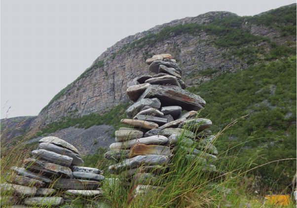
Kamienne trolle, Finnmark
(fot. E. Cisek)
Stone trolls, Finnmark
(photo by E. Cisek)