2025
3(83)
Michał Szczęsny Pelczarski*
Inverse modelling as a tool in teaching the conceptual formation
of synergistic architectural and structural forms
– exploring the reception of the method
DOI: 10.37190/arc250312
Published in open access. CC BY NC ND license
Abstract
The article describes the author’s experiences in teaching the creation of synergistic architectural and structural forms, meaning those where the ar-
chitectural form and the structural form are unied. A key factor is the unity in practice achieved through proper collaboration between the architectural
and structural professions.
The author, as a civil engineer with experience in teaching structural design at the academic level to architecture students, found that methods based
on physical modelling have proven to be very eective, particularly those employing reverse shaping. The article presents a teaching method based on
these principles and describes its results. The author also analyses students´ perception of the inverse shaping (form-nding) method, comparing the
advantages and disadvantages reported by nearly 90 students.
Currently, the process of educating civil engineers rarely utilizes manual physical modelling methods as a tool for shaping architectural and structural
form. For these purpose, computational methods and digital modelling are primarily used. In the author’s opinion, these methods are only suitable for the
second stage of project verication, after the initial creation of a unique concept. Similar conclusions can be drawn by observing the design workshop
and the work of famous designers, who often combine the skills of an engineer and an architect. A properly constructed physical model, developed at
the initial stage of design in close cooperation between the architect and the structural engineer, may already contain approximately 70% of solutions
consistent with the project’s ideology. Therefore, they can serve as a basis for further stages of designing a synergistic architectural and structural form.
Key words: shaping of the structure, structure’s architecture, physical modelling, architectural-structural form, ow of forces
Introduction
The development of construction, initiated by the indus-
trial revolution, brought about the end of an era in which
the terms “engineer” and “architect” meant the same thing.
A new relationship emerged between architects and struc-
tural engineers, which led to a separation of competences in
common design and construction practice and frequent an-
tagonism between these misunderstood specialists. Respon-
sibility for the design process has shifted from one to two
people, and this has given rise to the need for dialogue to
achieve a unied view. However, its participants must have
common ground – so that the conceptual design stage is not
lost (Todisco 2016). This crucial stage is based on a holis
-
tic, creative view, qualitative analyses and synergies, rather
than the dominance of one party. Exceptions are the few
outstanding creators, called structural artists by David P.
Billington (1985), among them Rafael Gustavino, Antonio
Gaudí, Robert Maillart, Pier Luigi Nervi, Eduardo Torroja,
Félix Candela, Eladio Dieste, Nikolaus Otto or Heinz Isler,
who combined architectural, engineering and construction
skills – and thus created works that have gone down in ar-
chitectural and construction history.
Interviews with Wacław Zalewski (Zalewski, Allen and
Iano 1998), an eminent Polish engineer and professor at the
Department of Architecture at MIT, show that he clearly
noticed this discrepancy, as well as the fact that the lack of
a common ground does not favour the achievement of syner-
gistic, high-quality design eects on the part of both profes-
sions, which are equally responsible for creating architectural
* ORCID:
0000-0002-4563-4694. Faculty of Architecture, Wrocław
University of Science and Technology, Poland, e-mail: michal.pelczarski@
pwr.edu.pl
122
Michał Szczęsny Pelczarski
and structural forms. In view of the above, they should work
closely together, especially in the rst, crucial, conceptual
phases of the design process.
The author’s many years of experience in developing
an awareness of the synergy of architectural and structur-
al forms among students of the Faculty of Architecture at
Wrocław University of Science and Technology shows
that the best way to achieve this goal is through physical
modelling methods, especially since manual skills are de-
clining among young people. This is because these meth-
ods engage – already in the initial stages of the conceptual
search for form – the natural perceptual abilities, the ability
to experience and intuitively predict the behaviour of ma-
terial form in the eld of external forces, the spatial imag-
ination and the creative potential of the designer (Ilkovič,
Ilkovičová and Špaček 2014). Gaudí, in his statements, re-
veals that man can think mainly in two dimensions. Only
the sight and touch of a nished object allow him to truly
understand space (Hensbergen 2015, 250). The use of so-
phisticated software at the stage of conceptual form-seek-
ing (Popovic Larsen, Tyas 2003), which supports the cal-
culation of forces and deformations in construction, and
various types of form generators, will therefore never re-
place the independent, physical modelling of matter. As
Zalewski said, the computer method does not, after all,
produce the form it investigates, despite advanced research
in this direction (Mueller, Fivet and Ochsendorf 2015;
Mueller, Ochsendorf 2011; Gedig 2010). This form has to
be materialised in an earlier process, when only qualitative
analysis is sucient When creating a model, the physical
designer, like a sculptor, moulds the material in specic
spatial congurations; he or she simultaneously controls
aesthetics, plasticity, rigidity and functionality. Any soft-
ware incorporated into the design process at this stage will
interfere with the already advanced, often subconscious
process going on in his mind.
State of research
The history of the application of methods for the shaping
of momentless forms intended for natural materials (stone,
clay, ceramics, brick) that do not stretch, according to mod-
ern knowledge, is as follows. The rst “creator” of this type
of form is nature, which eliminates the stretched parts of
matter through erosion. The result is then highly durable
arched or dome-shaped rock formations, known from moun-
tain or coastal caves, shaped in the earth’s eld of gravity so
that only compression occurs in their cross-sections. It is
most likely that man picked up on these forms and tried to
imitate them, initially by trial and error and, over time, in
a more rened and precise way. The hanging chain method
(at hanging model) was used by Robert Hooke in 1675
and Giovanni Poleni in 1748 to determine momentless pro-
les of arches and domes. To achieve purely compressible
forms, Antoni Gaudí used three-dimensional hanging mod-
els (made of strings and sandbags) between 1880 and 1926,
notably in the design of the Colònia Güell and intuitively
in the Park Güell (the landmark here is the use of inclined
columns and curving in line with the pressure line of the
retaining wall – the Portico De La Lavandera).
For further work, the Catalan architect used measure-
ments, reversed photographs and probably a mirror reec-
tion. Heinz Isler, on the other hand, worked between 1950
and 1960 on hanging reversed cloth membranes, coated with
plaster and then dried or poured with water and frozen, to
obtain funicular forms after reversal, used in the design of
momentless, extremely slender reinforced concrete shells
with large spans.
Contemporary “convenient” experimental physical me-
th ods used for the conceptual design of funicular structures
are realised by the author with students by constructing an-
ti-funicular rib physical models or anti-funicular shell mod-
els. The former are realised from chains of dierent weights,
reecting proportionally the level of materiality of the struc-
tural elements (ballasted, for example, with plasticine at the
points of future concentrated forces), then stiened with hot
glue or resin. The latter are formed from a combination of
chains and gauze coated with dental plaster.
In the digital world, tools are being developed for the
early stages of mesh mould design, such as CADenary, TL
Catenary, JTB Catenary, Grasshopper Catenary and Kanga-
roo or Food4Rhino-Spider, which simulate the behaviour
and geometry of hanging models and allow relatively easy
parametric exploration of moulds. There are also programs
based on the force density method (FDM), among them:
Rhino Vault 2, Sostik, Easy or Tensyl, Formnder, and
the thrust network analysis (TNA) method from the Block
Research Group at ETH Zurich, used in Rhino Vault and
Compas.
The use of such software and physical modelling has
enabled some exceptional contemporary developments.
These include the stone-built exceptionally large Global
Vipassana pagoda in Mumbai (96 m high and 85 m in di-
ameter dome; inside it accommodates approx. 8,000 peo-
ple), the steel-tubed, single-skin atrium at the Smithsonian
Institution in Washington, D.C., the Great Courtyard at the
British Museum in London (Schlaich Bergermann Partner
and Foster+Partners) and the impregnated cardboard tubes
for the Japanese Expo 2000 pavilion in Hanover (designer:
Shigeru Ban).
Basic concepts of inverse modelling method theory
Physical model
The physical model is understood here as a material
structural system, made on a reduced scale, reecting the
spatial form and mode of operation (in terms of force trans-
mission) of a real building object on a real scale of 1 : 1.
The author’s many years of experience in teaching conrm
the usefulness of physical modelling in developing struc-
tural awareness among students of architecture. The great
advantage of this method is that it can be used by almost
anyone, even an inexperienced user with only a prelimi-
nary knowledge of structural mechanics theory. All that is
needed is to follow a few basic principles, and the results
quickly illustrate the play of forces at the initial stage of the
conceptual search for form. The simplied model, which is
easy to make from commonly available materials, allows
many ideas to be tested, encouraging experimentation. This
Inverse modelling as a tool in teaching the conceptual formation of synergistic architectural and structural forms
123
allows observation of the behaviour of the assumed form
of the object under load, as well as qualitative assessment
of the structural system and its rapid verication. Constant
physical contact with the model fosters a subconscious pro-
cess of creating modications to the model and immediately
applying new solutions to it. It also contributes to maintain-
ing the high emotional involvement required to create new
solutions. However, the so-called reverse modelling, used
by the author in his work with students, plays a special role
in physical modelling.
Thrust line theory
Inverse modelling, in the form of planar or spatial mod-
els, is known in the literature as the hanging models meth-
od (Rippmann 2016), the catenary and the line of thrust
(Graefe 2021), inverted tensile models (Tomlow 1989) or
anti-funicular structures (Todisco 2016). This method was
used, for example, by Gaudí when he designed the church
in Colonia Güell, and his model was faithfully attempted
to be reproduced in 1989 by a team led by Frei Otto (Tom-
low 1989). In contrast, a contemporary method of inverse
shell formation was used by Heinz Isler (Campbell et al.
1980; Chilton 2001). Knowledge of the pressure lines is
particularly important in materials incapable of carrying
tension (stone, brick), limits the occurrence of corrosion
of scratch-sensitive materials (reinforced concrete), but
also allows the design of material-economical momentless
structures. It is worth mentioning that exural load-bearing
elements are less ecient than tensile ones in terms of util-
ising the strength properties of the load-bearing structure
material.
The mechanics of stone and brick arches, which are sen-
sitive to the tension arising during bending, is brilliantly
discussed in his work by Santiago Huerta (2005). In it, the
author investigates the ultimate load capacity of arch struc-
tures using models. This makes it possible to observe the
eects of pressure lines approaching the inner or outer edge
of the arch, leading to the formation of hinges in the arch.
Particularly noteworthy is the earthquake simulation meth-
od implemented on a hanging model by tilting the support
lines by, for example, an angle of ±15°.
In the methodology of physical, preliminary modelling
of structural forms, the full analogy between the drawing
line and the pressure line reecting it is essential. Both lines
represent the resultant action of all forces acting on the ob-
ject under investigation.
Physically, the tension line is a virtual accid rope or
chain (i.e., funicular line) arising in a structural element
from a load applied to it, causing it to stretch (Kuś 2008;
Mueller, Ochsendorf 2011; Mueller, Fivet and Ochsendorf
2015). For the forces, this line represents the only possible
“transmission channel”, beyond which they are unable to
physically “pass” between the supports.
Each change in load changes the geometry of the rope,
creating the image of a new and unique string line as a new
system in static equilibrium. The line of draughts also ap-
pears in graphical statics as a string polygon, i.e., a graph-
ical system that balances the concentrated loads acting on
the object.
By creating an object of structural material within de-
ned boundaries in space, we reduce the number of possible
string lines or pressures that can physically pass through that
object. The designer’s objective may therefore be to adapt
the geometry of the structure so that these lines, arising from
all possible loads and their real combinations, run in the vi-
cinity of the core of the cross-section – for the lines that run
in the cores of the cross-sections of the structure under study
induce in them only tension or only compression. When, on
the other hand, the pressure or tension line goes outside the
section core, the section is subject to bending. The section
bres closer to the pressure line will be compressed and on
the opposite side will be stretched.
Thus, if the designer, for various reasons, cannot main -
tain the pressure line in the core area or even in the cross-sec-
tional area, he or she has to reckon with an increase in the
volume of structural material required to carry the bend-
ing in that section where the line will extend beyond the
structure (the greater the further the line is from the axis
of the cross-section). It is this excessive deformation that
will force the designer to use more material in order for the
structure to meet performance and safety requirements.
The modelling of this type of semi-funicular solution
amounts to creating truss systems inside the available con-
tour. A rod-and-column system is then created, redirecting
the naturally formed funicular ows of force into the de-
signer’s accessible contour. The geometry of such semi-fu-
nicular constructions is based on parabolas, so that the axial
forces created in the top and bottom bands of this structure
are often of constant value.
This is because the distance between bands (i.e., the in-
ternal force arm) in parabolic systems is proportional to the
parabolic bending moment diagram. The constant force in
the bands of such a truss theoretically means that there is
no need for diagonal trussing and allows the use of a single
section along the length of the truss, such as a xed diameter
tube, which aects the architecture of the overall structure.
Inverse modelling method
– conclusions and a methodology
From the ndings of the theory of lines of pressure and
lines of drag demonstrated above, concerning the full anal-
ogies occurring between them, it follows, benecial for the
design of structures, that the path of static equilibrium be-
tween the forces acting on the designed object in the space
between supports can be considered in an inverted state, so
as to take advantage of the features of the chain curve giving
an image of the line of drag.
By inverting the modelled object or reversing only the
direction of the forces, it is therefore possible to simulate
the action of dead weight, ground pressure, water and wind
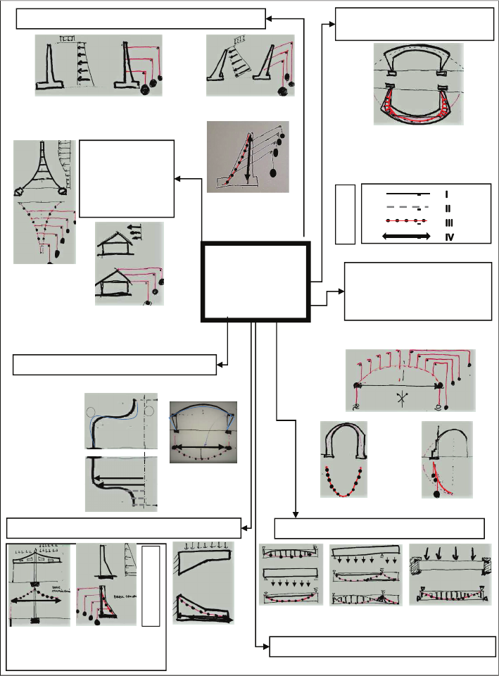
pressure on the designed structure (Fig. 1).
Inverse modelling makes it possible to visualise how, un-
der load in the contour accessible to the structure, cooper-
ative compressive force streams and tensile force channels
form. Systems built in this way are usually close to optimal,
due to the amount of material needed to ensure a favourable
ow of forces from the structure to its foundations. It is, of
course, possible to create many other geometries of force
124
Michał Szczęsny Pelczarski
Fig. 1. Catalogue of selected
applications of inverse modelling
in structural analysis and design
(elaborated by M. Pelczarski)
Il. 1. Katalog wybranych
zastosowań modelowania
odwrotnego w analizie
konstrukcji i w projektowaniu
(oprac. M. Pelczarski)
I – thin line: flexible connector used to suspend and hang, through deviators, the ballast simulating an external
load; thicker line: flexible connector forming and stabilising semi-funicular and/or funicular bands in a bar-ten-
sion truss system, visible in the working diagram of the frame and beams
II – flexible connector which, when the model is inverted to its final position, will act as a bar or compression ring
III – flexible connector (chain) loaded with ballast to simulate the self-weight of the arch, which after reversing
the direction of the forces or after inverting the model to the target position will be a funicular or semi-funicular
compression band
IV – a strut which, when inverted to the target position, will act as a tensile element in the form of a tie or
reinforcement in plane systems, or a ring in spatial systems
ux systems in the available contour, but these will consume
more material as they move away from the optimum systems.
The observation of the play of forces and the shaping of
structural forms that are most favourable in terms of force
ows can be carried out on 2D planar models or, for more
complex structures, on 3D spatial models, as Gaudí has
done (Huerta 2006).
With only a qualitative type of model analysis in mind,
the cross-section of the object to be analysed is divided into
strips, e.g., of equal width, and the ballast weights are se-
lected in proportion to the area of the structure delimited by
the strip in question. These elds, cut out of cardboard, are
numbered and suspended from a chain where it intersects
the centreline of the strip in question. Equal elements, e.g.,
washers or nuts, come in handy when applying the princi-
ple of proportional incremental loading, e.g., reecting the
length of a band of matter or ground pressure with increas-
ing depth.
In general, the inverse shaping method can involve pro-
ceeding iteratively in a ve-step process:
REVERSE
MODELLING
AREAS OF
APPLICATION
WHEN THE FUNICULAR FLANGE OF A
GIRDER OR RETAINING WALL IS IN
TENSION, INVERSION OF THE MODEL OR
FORCES IS NOT APPLIED
SIMULATION OF CANTILEVER BEHAVIOUR
SHAPING OF A
COMPRESSED
FUNICULAR FLANGE
REQUIRES INVERSION
OF THE MODEL
SIMULATION OF RETAINING WALL LOADING
EARTH PRESSURE WITHOUT
FRICTION
EARTH PRESSURE WITH
FRICTION
SIMULATION OF FRAME
BEHAVIOUR
SEMIFUNICULAR CHAIN ADAPTED
TO THE OUTLINE GEOMETRY OF
THE GIVEN SPACE, THANKS TO THE
STRUT-AND-TIE SYSTEM
SIMULATION OF SELF-
WEIGHT, BUTTRESS AND
FLYING BUTTRESS
ACTION
FORCE INVERSION
SIMULATION
OF
WIND LOAD
AND / OR
SELF-WEIGHT
EIFFEL TOWER
–
SHAPING OF
THE
FUNICULAR
GIRDER
SIMULATION OF RINGS IN A DOME
HORIZONTAL EDGE
GIRDER OF A HALL
SIMULATED WITH A
PROP
TENSION RING
SIMULATED
WITH A PROP
COMPRESSION RING
SIMULATED
WITH A TIE
SIMULATION OF BEAM BEHAVIOUR
SIMPLE BEAM
(TYPE 1 AND 2)
FIXED BEAM
CANTILEVER BEAM
(TYPE 1 AND 2
)
SIMULATION OF EARTHQUAKE EFFECTS
MASSIVE WALLLS
DESCRIPTION
IN THE TEXT
LEGEND
PINNACLES – BUTTRESSES
MODEL INVERSION
OR
OR INVERTED MODEL ROTATED BY AN ANGLE OF 10–15°
SHAPING
OF COMPRESSED
FUNICULAR
GIRDER
EXCEPTIONS
+
-
Inverse modelling as a tool in teaching the conceptual formation of synergistic architectural and structural forms
125
– Stage I: Initial denition of the designed function-
al-spatial form in the form of a template model.
– Stage II: Inversion of the assumed model (or direction
of forces), followed by shaping of the chain curves (lines
of pull) by gravity so that the chain falls within the area of
the template, and recording of the achieved result from the
dead weight.
– Stage III: Loading with a set of expected alternating
loads (as these often signicantly alter the geometry of the
predetermined drawing line conguration) and then record-
ing the new drawing line layout.
– Stage IV: Comparison of the results of stages II and III,
followed by an adjustment of the ballast values at critical
points, where the drawing line approaches or goes beyond
the edge of the bar-band. This corresponds to a proportional
change in the width of the critical section in question or to
the application of ballast in the form of, for example, a pin-
nacle or lantern or other ornamentation that is also architec-
turally advantageous. The changed section geometry should
ensure that the chain curves run as close as possible to the
central zone of the section, i.e., in the core of the section.
– Stage V (optional): Working on the inverted model and
inputting the digital model, possibly scanning or stiening
the chain model by covering it with, e.g., resin or hot glue
and inverting the model to the target position.
Description of own research
Principle of instruction and examples
of student work using the inverse modelling method
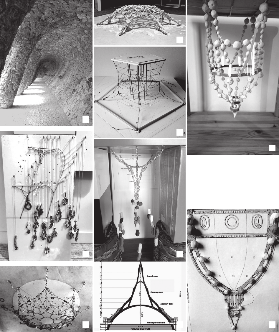
Selected examples of work (Fig. 2) were carried out by
students completing assignments under the guidance of the
author as part of the course “Structures in contemporary
architecture” during the master’s degree programme at the
Faculty of Architecture, Wrocław University of Science and
Technology in the winter semester 2021. The modelling as-
signment is usually conducted in several stages. These are
as follows: selection of one of approximately 60 topics, re-
search of available information materials on the selected ob-
ject, construction of a 2D at model demonstrating the op-
eration of the main structural system, construction of a 3D
model in a simplied version (A4 format), introduction by
the student of the author’s innovation and construction of
the target model (A3 format), preparation of a report on the
course of the research work, its stages, corrections, history
of good and faulty solutions, techniques applied and an in-
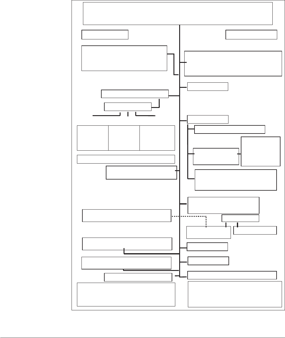
ventory of materials used (Fig. 3).
A very important stage undertaken during the course: the
analysis of the work of the structure allows students to fa-
miliarise themselves with the possible force ow systems
in an existing prominent object, and enables them to shape
and make their own modications to it. At this stage Inverse
modelling enables students to design structures with a high
economy of materials and an architecturally attractive ex-
pression of forces, which consists in making the structur-
al system explicit in the architecture of the building. The
inability to apply the inverse method explicitly during the
analysis or creation of a given object indicates that the struc-
ture – or rather its form and geometry – is moving away
from funicular systems, which implies the need for semi-fu-
nicular and/or funicular truss systems with a larger volume
of structural material and a less clear system operation for
the observer.
Summary
– conclusions and demands
One of the most important factors determining the quality
of an architectural work and its sustainable ecological cha-
racteristics is the unity between functional-spatial form and
the structural form it represents. The two professions, archi-
tecture and construction, should work more closely together,
especially during the formation phase of a common design
concept. Both are equally responsible for creating a synergi-
stic architectural and structural form. This requires, among
other things, the strengthening of architectural awareness
on the part of the constructors and, conversely, of structural
awareness on the part of the architects, and its development
should begin at a very early level of academic education.
Based on this conviction, the author postulates the need for
more extensive training in this area than is currently the case
at the faculties of building and architecture. The creation of
a new course of study is also worth considering: “design of
synergistic architectural-structural forms” and, in the long
term, perhaps even a new professional specialisation.
The above statements form the ideological basis of the
author’s scientic and didactic activities at the Faculty of Ar-
chitecture of Wrocław University of Science and Technology.
They are also the basis for searching for the most appropriate
methods of teaching architecture students to understand the
work of structural systems and their inuence on architectur-
al forms. From the author’s 10 years of teaching activity, it
is evident that the methods using physical modelling, espe-
cially using inverse shaping, produce the best results. They
are well adapted to the perceptual and creative abilities of
future architects, and are similar in terms of technique to the
methods used in basic subjects teaching architectural design
skills. The executional simplicity of the models makes stu-
dents perfectly capable of building them at home, and the
general friendly principles of physical modelling allow them
to carry out the required range of analyses and experiments
and reach valuable conclusions on their own (see Fig. 3).
During the project, the student’s relationship with the in-
structor is more personal and more frequent; the instructor,
via a popular instant messenger, can provide precise com-
ments and graphic, audio and video comments at key mo-
ments for the student. An important value is the students’
inventiveness in solving micro-engineering problems, often
used when constructing models on their own under condi-
tions of an always limited budget.
The scope of the term paper closure report on structur-
al modelling requires students to comment on their chosen
modelling method. Among the positives, they mention the
use of spatial models, which facilitates, among other things,
an understanding of how a system works, examining it
with the sense of sight and touch. They also considered it
valuable to simulate the operation of well-known structures.
They often pointed out that research work during mod-
elling, based on experience, strengthens condence in one’s
126
Michał Szczęsny Pelczarski
Fig. 2. Inverse modelling – selected examples of student work:
a) inspiration: retaining wall according to the design of A. Gaudí, Park Güell in Barcelona (photo by M. Pelczarski),
b) analysis of the inspired cross-section using inverse modelling (reversing the direction of forces,
ballast is in the form of steel nuts which simulating earth pressure with friction, the main line of thrust/tension is created
as a loop stretched by inverted forces from soil pressure
– terrace cantilevers shaped by struts forming a funicular compression flange (author: A. Łuksik),
c) inverted chain model of Nervi’s dome, Palazzetto dello Sport (Little Sports Palace) in Rome,
d) chain model fixed withplaster (author: K. Indyk),
e) author’s proposal of a simplified inverse model representing the structural work of the water tower,
Fedala Reservoir in Mohammedia, Morocco (author: U. Śliwińska),
f) inverse model of the Global Vipassana Pagoda in Mumbai (2009),
g) sketch of the actual structure, a hall for 8,000 people, monitored by the Auroville Earth Institute studio (author: S. Krawczyk),
h) model inspired by the dome of Santa Maria del Fiore in Florence, Italy (architect: Filippo Brunelleschi),
i) flat cross-section model at the location of the tension ring with an applied strut (authors: E. Naworska, S. Kiciński, W. Włodarczyk)
a
d
e
h
f
g i
b
c
Inverse modelling as a tool in teaching the conceptual formation of synergistic architectural and structural forms
127
Il. 2. Modelowanie odwrotne – wybrane przykłady prac studenckich:
a) inspiracja: ściana oporowa według projektu A. Gaudíego, Park Güell w Barcelonie (fot. M. Pelczarski),
b) analiza inspirowanego przekroju za pomocą modelowania odwrotnego (odwrócenie kierunku działania sił,
balasty w postaci nakrętek stalowych symulujących parcie gruntu z tarciem
– wsporniki tarasów kształtowane z rozpór tworzących funikularny pas ściskany
(autorka: A. Łuksik),
c) odwrócony łańcuchowy model kopuły Nerviego, Palazzetto dello Sport w Rzymie,
d) model łańcuchowy usztywniony gipsem (autorka: K. Indyk),
e) autorska propozycja uproszczonego modelu odwrotnego przedstawiającego pracę konstrukcji wieży ciśnień Fedala Reservoir w Mohammedia,
Maroko (autorka: U. Śliwińska),
f) model odwrotny Global Vipassana Pagoda w Bombaju (2009),
g) szkic przekroju hali na 8000 osób monitorowanej przez studio Auroville Earth Institute (autor: S. Krawczyk),
h) model inspirowany kopułą Santa Maria del Fiore we Florencji (architekt: Filippo Brunelleschi),
i) model płaski przekroju z rozporą zastosowaną w miejscu pierścienia rozciąganego (autorzy: E. Naworska, S. Kiciński, W. Włodarczyk)
Student’s own guidelines for building a 3D model
PROBLEM NO. 1
PROBLEM NO. 2
PROBLEM NO. 3
● Research on the available documentation of
the facility.
● Information about designers and their inspirations.
● Development of a work pattern of the structure.
● Verification of correct understanding of structure
work in the selected facility
● Proposed scope and type of research
● Verification of model
construction technic
● Support for innovation
concept
PHYSICAL MODELING OF THE SYNERGIC ARCHITECTURAL / STRUCTURAL
FORMS
● METHODOLOGY OF THE DIDACTIC PROCESS ●
TUTOR
STUDENT
CONSULTATION 5
SUMMARY – FINAL CONCLUSIONS
● 3D model verification
(A4 base + details)
● Assessment of the innovation of the form
● Assessment of the innovation of the structure
● Assessment of architectural and construction
synergy
● Evaluation of the technological innovation of the
model
CONSTRUCTION OF THE 3D MODEL
OF THE AUTHOR'S OBJECT (the base: A3)
ELABORATION OF THE REPORT
● Weaknesses and strengths of the modeling method
used
● Chronological documentation of the modeling
● Applied materials ● Conclusions for the future
CONSULTATION 3
● Verification of the 3D model,
(base: A4)
CONSULTATION 4
● Choice of 3D model construction
technology
● Contact with models photo archive
● Physical contact with archival models
CONCLUSIONS
Ending the task
Continuation
of the task
CONSTRUCTION OF A 3D MODEL
the base of the model: A4
A PROPOSAL OF OWN FORM, INSPIRED BY
AN EXISTING OBJECT
CONSTRUCTION OF THE 3D MODEL
OF THE AUTHOR'S OBJECT (the base: A4)
● inspiration by form ● inspiration by structure
PRESENTATION OF THE GENERAL
ASSUMPTIONS OF THE COURSE
Handing over a catalog of 60 topics (database of
existing facilities: stadium, hall, pavilion, engineering
facility)
SUBJECT SELECTION AND ITS INITIAL
ANALYSIS
The student has the option of submitting his
own proposal of a topic that is not included in
the tutor's catalog.
CONSULTATION 1
CONSULTATION 2
CHOICE
OF PHYSICAL
MODELING METHOD
MODELING:
● classic
● inverted
● membranes
● rod-tension
structures
VERIFICATION OF CONCLUSIONS
CONSTRUCTION OF A 2D MODEL
MODEL RESEARCH
●
Searching for
the maximum
stiffness of
the model
●
Recognition of
justifications
for the used
solution
●
Searching for
synergy of
architectural and
structural forms
Fig. 3. Physical modelling
of synergistic architectural and
construction forms
– a methodology of
the teaching process
(elaborated by M. Pelczarski)
Il. 3. Modelowanie
fizyczne synergicznych form
architektoniczno-konstrukcyjnych
– metodyka procesu dydaktycznego
(oprac. M. Pelczarski)

128
Michał Szczęsny Pelczarski
own intuition. On the other hand, they mentioned the fol-
lowing as disadvantages: labour-intensive, the need for
manual precision, patience, the need for assistance from
another person, confusion resulting from the reversal of
forces. There were also comments about the benecial ef-
fect of physical contact with a collection of models made in
previous years, which allows a quicker understanding of the
working principles of physical models through touch and
the models’ reactions to the applied force. The advantages
and disadvantages of the inverse shaping method reported
by nearly 90 students and the author are summarised in Ta-
ble 1 (the advantages outweigh the disadvantages, and the
indicated disadvantages are solvable).
The research shows that this method, properly commu-
nicated to students and supported by interactive exercises
or scripts available on the web, can contribute to a signif-
icant increase in their self-reliance and condence when
designing new, as yet unknown optimal forms that can be
independently veried by them using the inverse modelling
technique. The modelling of new forms based on the phys-
ical laws of nature used during inverse modelling should
and, as the research shows, can become a cornerstone of the
contemporary architect’s workshop, making him or her an
informed creator of new solutions, well prepared for dia-
logue with all branches of the design process.
References
Billington, David P. The Tower and the Bridge. The New Art of Structur-
al Engineering. Princeton University Press, 1985.
Block, Philippe, Matt DeJong, and John Ochsendorf. “As Hangs the
Flexible Line: Equilibrium of Masonry Arches.” Nexus Network
Journal 8, no. 2 (2006): 13–24. https://doi.org/10.1007/s00004-006-
0015-9.
Campbell, Bruce, Allen Rosenbaum, Heinz Isler, and David Billington.
Heinz Isler as Structural Artist. The Art Museum, Princeton Univer-
sity, April 1–May 11, 1980. An Exhibition. The Museum, Princeton
University, 1980.
Chilton, John. The Engineer’s Contribution to Contemporary Architec-
ture. Thomas Telford, Riba Publications, 2001.
Gedig, Michael. “A Framework for Form-Based Conceptual Design in
Structural Engineering.” PhD diss. The University of British Co-
lumbia, 2010.
Graefe, Rainer. “The Catenary and the Line of Thrust as a Means for Shap-
ing Arches and Vaults.” In Physical Models. Their Historical and
Current Use in Civil and Building Engineering Design, edited by Bill
Addis. Ernst & Soon, 2021. https://doi.org/10.1002/9783433609613.
ch3.
Hensbergen, Gijs van. Gaudi – geniusz z Barcelony. Translated by Iwona
Chlewińska. Wydawnictwo Marginesy, 2015.
Huerta, Santiago. “Structural Design in the Work of Gaudí.” Architectur-
al Science Review 49, no. 4 (2006): 324–39. https://doi.org/10.3763/
asre.2006.4943.
Huerta, Santiago. “The Use of Simple Models in the Teaching of the Es-
sentials of Masonry Arch Behaviour.” In Teoria e pratica del costru-
ire. Saperi, strumenti, modelli. Esperienze didattaiche e di ricerca
a confront. Seminario internazionale: Ravenna 27–29 ottobre 2005
/ Theory and Practice of Construction. Knowledge, Means, Models.
Didactic and Research Experiences. International seminar, edited
by Giovanni Mochi. Moderna, 2005.
Ilkovič, Ján, Ľubica Ilkovičová, and Robert Špaček. “To Think in Ar-
chitecture, to Feel in Structure: Teaching Structural Design in the
Faculty of Architecture.” Global Journal of Engineering Education
16, no. 2 (2014): 59–65.
Kuś, Stanisław. “Ogólne zasady kształtowania konstrukcji.” In Bu-
downictwo ogólne. Vol. 3: Elementy budynków, podstawy projek-
towania, edited by Lech Lichołaj and Grzegorz Bajorek. Arkady,
2008.
Disadvantages Advantages
Labour-intensive Simple and proven techniques for making physical models
Need for manual precision Strengthening of intuition
Assistance by another person required Bolder and independent design
Difficulty in force reversal interpretation Further development of research tools
High cost of experiments Independent evaluation of one’s own solution
Better understanding of the workings of the design used
Ability to introduce modifications to the model
Simultaneous control over form, function, and structure
Developing design decision-making skills
Searching for new modelling techniques
Adaptation of the method to the students’ perceptive abilities
Encouraging micro-engineering problems solving
Table 1. Study of students’ reception at the faculty of architecture of reverse modelling methods as a tool for designing optimal architectural
construction forms (elaborated by M. Pelczarski)
Tabela 1. Wady i zalety modelowania fizycznego synergicznych form architektoniczno-konstrukcyjnych
przy zastosowaniu metody modelowania odwrotnego (oprac. M. Pelczarski)
Inverse modelling as a tool in teaching the conceptual formation of synergistic architectural and structural forms
129
Mueller, Caitlin, Corentin Fivet, and John Ochsendorf. Graphic Statics
and Interactive Optimization for Engineering Education. In Pro-
ceedings of the 2015 Structures Congress, April 23–25, 2015, Port-
land, Oregon. Association for Computing Machinery, 2015. https://
doi.org/10.1061/9780784479117.223.
Mueller, Caitlin, and John Ochsendorf. “An Interactive Evolutionary
Framework for Structural Design.” In Conference: 7
th
International
Seminar of the IASS Structural Morphology Group (SMG 2011),
London, UK, September 17–18. Accessed August 28, 2025, at
https://www.caitlinmueller.com.
Popovic Larsen, Olga, and Andy Tyas. Conceptual Structural Design.
Bridging the Gap between Architects and Engineers. Thomas Tel-
ford, 2003.
Rippmann, Matthias. “Funicular Shell Design Geometric Approaches
to Form Finding and Fabrication of Discrete Funicular Structures.”
PhD diss. ETH Zürich, 2016, No. 23307.
Todisco, Leonardo. “Funicularity and Equilibrium for High-Performance
Conceptual Structural Design.” PhD diss., Technical University of
Madrid, School of Civil Engineering, 2016.
Tomlow, Jos. IL 34 Gaudi. Das Modell, the Model, el Modelo. Institute
for Lightweight Structures, 1989.
Zalewski, Waclaw, Edward Allen, and Joseph Iano. Shaping Structures.
Statics. John Wiley & Sons, 1998.
Streszczenie
Modelowanie odwrotne jako narzędzie w nauczaniu konceptualnego kształtowania synergicznych form architektoniczno-konstrukcyjnych
– badanie recepcji metody
W artykule autor przedstawił własne doświadczenia w nauczaniu kształtowania synergicznych form architektoniczno-konstrukcyjnych, czyli takich,
w których forma architektoniczna i forma konstrukcyjna stanowią jedność. Szczególną determinantę osiągania w praktyce tej jedności stanowią odpo-
wiednie relacje pomiędzy profesjami architektoniczną i konstrukcyjną.
Autor występuje z pozycji inżyniera budownictwa z wieloletnim stażem w nauczaniu konstrukcji na poziomie akademickim (studentów architektury).
Z jego doświadczeń wynika, że efektywne w tej mierze są metody wykorzystujące modelowanie zyczne, w tym tzw. kształtowanie odwrotne. W arty-
kule zaprezentował sposób prowadzenia zajęć opartych na tych właśnie podstawach i opisał przykłady uzyskanych podczas nich efektów. Autor zbadał
też recepcję metody kształtowania odwrotnego wśród studentów Wydziału Architektury Politechniki Wrocławskiej, zestawiając wady i zalety zgłoszone
przez blisko 90 osób.
Obecnie proces edukacji inżynierów budownictwa rzadko wykorzystuje manualne metody modelowania zycznego jako narzędzia kształtowania
formy architektoniczno-konstrukcyjnej. W tych celach stosuje się głównie metody obliczeniowe i modelowanie cyfrowe. Zdaniem autora metody te
są właściwe dopiero w drugim etapie werykacji konstrukcji, po wcześniejszym stworzeniu unikalnego konceptu i zarysu obiektu podczas wstępnego
modelowania zycznego. Do podobnych wniosków można dojść, obserwując warsztat i dorobek słynnych projektantów, łączących często równocześnie
kompetencje inżyniera i architekta. Model zyczny, zbudowany poprawnie już we wstępnej fazie projektowej i przy ścisłej współpracy architekta i kon-
struktora, może zawierać około 70% trafnych ideowo rozwiązań, a te mogą stanowić podstawę dalszych faz koncepcyjnego doskonalenia synergicznej
formy architektoniczno-konstrukcyjnej.
Słowa kluczowe: kształtowanie konstrukcji, architektura konstrukcji, modelowanie zyczne, forma architektoniczno-konstrukcyjna, przepływy sił