
2025
3(83)
Barbara Misztal*
On the variability in time of the longitudinal modulus
of elasticity E and the traverse modulus of elasticity G
and their impact on the rigidity of timber structures
DOI: 10.37190/arc250311
Published in open access. CC BY NC ND license
Abstract
The paper formulated the problem of lack of analysis of changes in rigidity over time, large-space constructions of glued wood, describing the dome
of Konohana Dome in Japan. On the example of a study of pine beams with a static support scheme, it was shown that on the basis of the bending mea-
surement it was possible to estimate the spring and form rigidity of the research model. It has been shown that with the increase in bending over time,
the moduli of longitudinal E and transverse G elasticity decreases. It has been revealed that the cause of the nonlinear increase in bending over time is
the decreasing rigidity of the spring and the shape of the support beam.
Key words: modulus of longitudinal rigidity, modulus of transverse rigidity, critical force, structural rigidity
Introduction
The building industry of glued wood has developed
dynamically since the forties of the 20
th
century, since the
development and implementation on industrial scale of
water-proof resorcinol glues on the basis of resins (RPF).
Since the seventies of the 20
th
century large-capacity facil-
ities having the function of sports and spectators halls have
been built. One of the examples is the little-known in Eu-
rope the multi-function spectators hall, Konohana Dome, at
Miyazaki in Japan. In the Polish and global references no
analysis in time of the rigidity of the construction of such
facilities has been found. Referring to the study by Zbig-
niew Kowal (1996) and using the analogy of the structure
of wood to the building of brous composites, the author
of this paper has conducted her own experiment, reveal-
ing that on the basis of the measurement of deections it is
possible to assess the tendency of variations in time of the
rigidity of wooden constructional elements and systems.
Description of the research problem
The large-spatial dome, Konohana Dome (Fig. 1), was
built in 2004 of glued wood (Iimura 2008). The facility
constitutes a big achievement in the eld of architecture,
building technology and construction. Bars of glued wood
were used therein, including thickset bars of a slimness of
λ < 20, connected with steel knots. The steel knots were
connected with wooden bars using steel sheets glued into
the wooden section. Despite noticing a range of negative
processes in such constructions, e.g., the increase in de-
ections of wooden elements in time without a rise in the
load, appearing, among others, in the dome at Portland,
USA (Misztal 2018), and the ssion of the bres of wood-
en bars in the zones at by steel nodes (Lachiewicz-Złotow-
ska, Orłowicz 2008), no recognition research is conducted
within the eld of a change in the rigidity of construction
wooden systems study in time.
The shape of the Konohana Dome was built with wood
glued in layers from December 2002 until March 2004. The
bars of the cantilever structure of a section 30 × 120 cm was
made of the quickly-growing tree: Japanese cryptomeria
(Sekkan-sugi, Cryptomeria japonica), appearing in the vi-
cinity of the city of Miyazaki, growing for at least 40 years
* ORCID:
0000-0001-7811-1331. Faculty of Architecture, Wrocław
University of Technology, Poland, e-mail: barbara.misztal@pwr.edu.pl
116 Barbara Misztal
since after that time the sugi wood gets the strength su-
cient to make the construction.
The dome having an elliptic shape of the horizontal projec-
tion has a diameter inside the projection of 122.0 ×
104.5 m
and the greatest height of 38.0 m. The total area of the pro-
jections amounts to 10,966.0 m
2
. The volume of the glued
wood, of which the wooden structure was made, amounts to
1,381.0 m
3
. The mass of the wooden structure as converted
into 1 m
2
of the projection, totals 42.80 kg/m
2
,
whereas the
mass of the steel, of which the knots were made (Figs. 1c, d)
and the steel structure that tightens the fabric constituting
the outside shell totals 44.70 kg/m
2
(Iimura 2008).
The construction of the dome is a steel-wood beam scaf-
folding having a double curvature. Such a system is an
arrangement of wooden bars susceptible to the action of
transverse forces in the sections by the steel knots, espe-
cially in thickset bars of a small slimness (Fig. 1d). In the
paper, Strength Performance of Glulam Made of Obi-sugi
Laminae with Low Young’s Modulus of Bending (Matsu-
moto et al. 2007), the method of determining the modulus
of elasticity E of sugi wood, of which the structure of the
dome at Miyazaki was described, however, the modulus of
transverse elasticity G was not determined. The variations
in time of the moduli of longitudinal elasticity E and that of
transverse elasticity G was not examined.
The domes made of glued wood, including the dome
at Miyazaki, are made of the natural brous composite, as
wood is. The brous composites behave, unlike homog
-
enous materials, such as steel. Kowal (1996) introduced
a model of the theoretical analysis of constricted composite
bars. When examining them, he found that the
shape of the
bar destruction depended on the bar slimness,
the properties
of bres and the matrix as described by the moduli of longi-
tudinal elasticity E and transverse elasticity G
as well as on
the value of the quotient E/G. Kowal discovered the para-
dox of the load carrying-capacity of composite bars: thick-
set composite bars of the slimness of λ < 20
show a lower
critical load capacity than those of a higher slimness, e.g.,
λ > 80. The graphs compiled by the author of the paper
(Misztal 2018) on the basis of the results of the study by
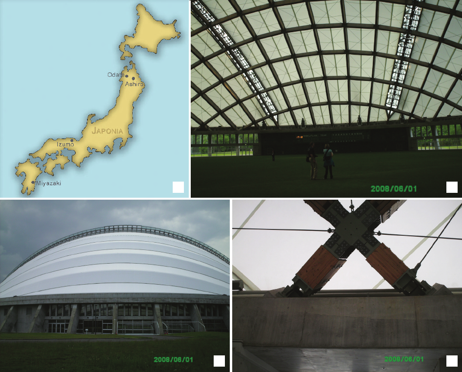
Fig. 1. Beam scaffolding, steel-wood Konohana Dome built with sugi wood in Miyazaki, Japan, 2004:
a) location of the Konohana Dome, b) view of the dome from the entrance side, c) view of the wooden structure from the inside,
d) view of the steel knot and constricted wooden bars in the support zone of the dome structure (photo by B. Misztal)
Il. 1. Ruszt belkowy, stalowo-drewniany kopuły Konohana Dome wybudowanej z drewna sugi w Miyazaki, Japonia, 2004:
a) lokalizacja kopuły, b) widok kopuły od strony wejścia, c) widok konstrukcji drewnianej od wewnątrz,
d) widok stalowego węzła i krępych prętów z drewna w strefie podporowej konstrukcji kopuły (fot. B. Misztal)
a
b d
c
On the variability in time of the longitudinal modulus of elasticity E and the traverse modulus of elasticity G 117
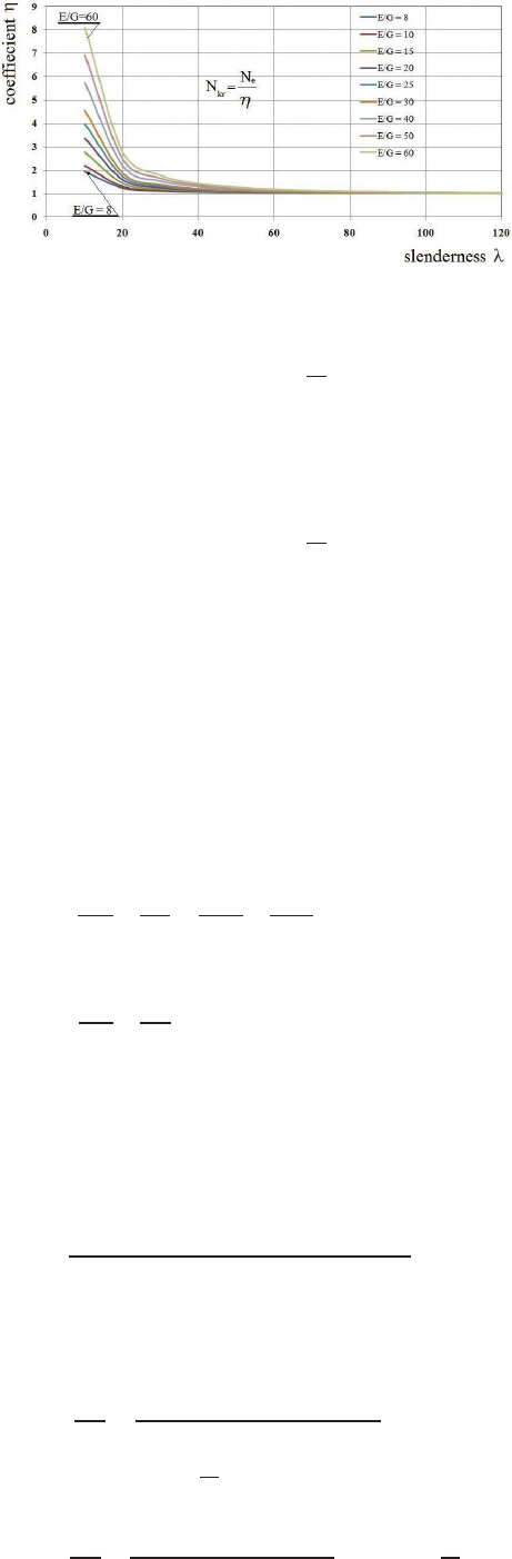
Kowal presents how grows the coecient decreasing the
load capacity η for bars of a slimness of λ < 20 (Fig. 2).
The coecient η is important since it tells us, how many
times the critical load-bearing capacity of a constricted bar
decreases depending on the slimness λ and on the relation
E/G according to the equation by Kowal.
Since wood is a natural brous composite, similar phe-
nomena should be expected as in articial brous com
pos-
ites. For these reasons the author of the paper has been deal-
ing, for many years, with the exploration of wood as a b
rous
composite, including the moduli of elasticity of wood.
In the referenced literature of this subject matter no re-
search by other authors has been noticed about a change in
time of the moduli of elasticity E and G of wood, as well as
on the critical load-bearing capacity of wooden structures
as well as the variations of their rigidity in time.
Considering the impact of wood (as reected by the mag
nitudes of E and G) on the aesthetics, durability and safety
of the facilities made of wood, the author of the paper con-
ducted her own experiment in order to show how changes
the value of the moduli of elasticity of wood in time. The
information on the moduli of elasticity, both longitudinal E
and transverse ones G, has the basic meaning for the devel-
opment of the large-spatial facilities made of glued wood,
the assessment of the rigidity and the load-bearing capacity
in time. The knowledge of the magnitudes of E and G pro-
vides a possibility to forecast in time the variations of an ar-
chitectonic form and the load-bearing capacity of a structure.
The objective of the research
The objective of the research conducted by the author of
this paper is to show that:
1. The tendency of the variations of the moduli of trans-
verse rigidity G and that of longitudinal elasticity E can be
diagnosed on the basis of the measurements of deections.
2. The rigidity of a wooden element changes in time.
Description of own research
Theoretical basics of the method
The author of the paper has dealt for many years with
the theoretical basics of the research about the moduli of
longitudinal elasticity and that of transverse elasticity. In
her publication dated 2020 (Misztal 2020), she specied
the algorithm to determine the values of longitudinal elas-
ticity E and that of transverse elasticity G, as well as she
examined the model of a spruce wood beam. Reminded in
this paper is the course of calculations of the moduli E and
G, in order to prove that the rigidity of a wooden element
varies in time. To this aim, the author of the paper conduct-
ed an experiment on two models of a cantilever beam made
of pine wood.
In the research scheme adopted for the research the
total deection of the supporting beam depends on the
bending rigidity EJ and on the shape rigidity FG of the bar
(E – modulus of longitudinal elasticity, G – modulus of
transverse elasticity, J – moment of inertia of the bar sec-
tion, F – cross-sectional area of the bar).
An experiment lasting for 72 hours was scheduled. The
examination of two cantilever beams having the length of
l
1
= 2l
2
and l
2
was conducted (2). The system of equations
(3) and (4) was arranged:
For the cantilever beam of the lenght l
1
= 800 mm, where
l
1
= 2l
2
(2)
(3)
For the cantilever beam of the lenght l
2
= 400 mm:
(4)
Cantilever beam’s cross-section:
Geometric moment of inertia of the cantilever beam’s
cross-section:
The coecients designated as A were introduced
– equation (5) and B – equation (6) (5)
(6)
Fig. 2. Graph of the reduction factor η for the critical load-bearing
capacity of compressed members according to equation (1)
(elaborated by Misztal 2018)
equation (1):s ssssssssss ss
N
kr
– critical load of the composite member, N
e
– Euler’s critical load,
η – reduction factor for the Euler-based critical load according to
classical mechanics (source: Kowal 1996)
Il. 2. Wykres współczynnika η zmniejszającego nośność krytyczną
prętów ściskanych według wzoru (1) (oprac. Misztal 2018)
wzór (1): cc cc
N
kr
– siła krytyczna pręta kompozytowego,
N
e
– siła krytyczna według Eulera,
η – współczynnik zmniejszający siłę krytyczną liczoną z wzoru Eulera
według zasad mechaniki klasycznej (źródło: Kowal 1996)
=
=
1
=
1
3
3
+
1
=
8
2
3
3
+
2
2
2
=
2
3
3
+
2
= 3.8 × 1.03 × 10
−4
m
2
= 3.914 × 10
−4
m
2
=
3.8 × 10
−2
[
m
]
×
(
1.03 × 10
−2
[
m
]
)
3
12
= 0.3460302 × 10
−8
m
4
=
3.8 × 10
−2
[
m
]
×
(
1.03 × 10
−2
[
m
]
)
3
12
= 0.3460302 × 10
−8
m
4
=
2
3
3
=
2.50×
(
40 × 10
−2
)
3
m
3
3 × 0.3460302 × 10
−8
m
4
= 15412912.9 [
N
m
]
=
2
3
3
=
2.50×
(
40 × 10
−2
)
3
m
3
3 × 0.3460302 × 10
−8
m
4
= 15412912.9 [
N
m
]
=
2
=
2.50× 40 × 10
−2
m
3.914 × 10
−4
m
2
= 2554.9 [
N
m
]
118 Barbara Misztal
The solution for the system of equation (3) and (4) are
equations (7) and (8)
, A – equation (5) (7)
, A – equation (5) and B – equation (6) (8)
The formulae for the accounting determination of the
values of the modulus of longitudinal elasticity E and that
of transverse elasticity G using the measured deections of
the model of the cantilever beam were obtained.
Research
Selected for the research were beams made of pine wood
in an air-dry state. The experiment was conducted in a room
of a temperature of 22°C and a humidity of ca. 40%. The
measurements of deections were performed on the free
end of the cantilever using an inductive sensor connected to
a computer on which the values of deections were recorded:
immediately upon the experiment for the time t
0
= 0.00, af-
ter the time t
1
= 0.75 hours, t
2
= 1.50 hours, t
3
= 3.00 hours,
t
4
= 12.00 hours, t
5
= 24.00 hours, t
6
= 48.00 hours, t
7
= 72.00
hours.
The rst research model had the following dimensions:
the cross-section of 1.03 × 38 mm, the length of 1,200 mm,
the second research model: cross-section 1.03 × 38 mm,
length 800 mm. The models were weighed before the ex-
periment. Considering a tiny mass, the own mass of the
models was omitted. Fastened on the rst research model,
on one end, was the model of the cantilever beam accord-
ing to the schematic shown in Figure 3a, having the length
of the cantilver of 800 mm.
The load of the value of m = 250 g was applied on the
free end of the cantilever perpendicularly to the plane of
the lower rigidity of the beam. The temporary deection
was measured immediately, which amounted to y
1
= 4.91
mm = 4.91 × 10
–3
m. After the time t
2
= 0.75 hours of the
impact of the deection was read out: it amounted to y
2
=
5.50 mm = 5.50 × 10
–3
m. The successive deections were
measured over the time of 72 hours of the experiment’s du-
ration and were listed in Table 1. The graph of the deec-
tions measured was shown in Figure 4.
Prepared for testing on the second test stand was another
model having the static schematic, as shown in 4a, of the
cantilever length of l
2
= 400 mm. The beam was fastened
on one end, whereas the another, free end was loaded with
a concentrated mass m = 250 g perpendicularly to the plane
of the lower rigidity of the beam, as shown on the schematic
in Figure 3b.
Immediately upon suspending the mass m = 250 g, the
temporary deection was measured in time t
0
= 0.00, the
temporary deection measured amounted to y
0
= 0.71 mm
= 0.71 × 10
–3
m. After the time t
1
= 0.75 hours, the im-
pact of the load was re-read, the impact of the deection
amounted to y
1
= 0.79 mm = 0.79 × 10
–3
m. Successive de-
ections were read out in the time of 72 hours and listed in
Table 1. The graph of the deections measured in function
of time is shown in Fig. 4.
Results of the testing
Listed in Table 1 are the deections measured during
72 hours of the experiment’s duration.
The total increase in deections of the model a cantile-
ver length of l
1
= 2l
2
= 800 mm during 72 hours amounted
to 2.64 mm, whereas that of the model of the cantilever
length l
2
= 400 mm amounted to 0.36 mm. The increases in
the deections decreases in time, however, no stabilization
of deections during 72 hours of the experiment’s duration
were noticed.
While substituting the magnitudes of the deections on
the free ends of the cantilevers as listed in Table 1 and as
shown in Figure 5 to the formulae (8) and (9), calculated
were the moduli E (formula 7) and formula G (formula 8)
of the pine-wood beam tested in the dry-air state. Listed in
Table 2 are the calculated values of the moduli, whereas
shown in Figure 5 is the graph of the decreasing of the val-
ues of the modulus of elasticity E and that of the modulus
of transverse rigidity in G in time.
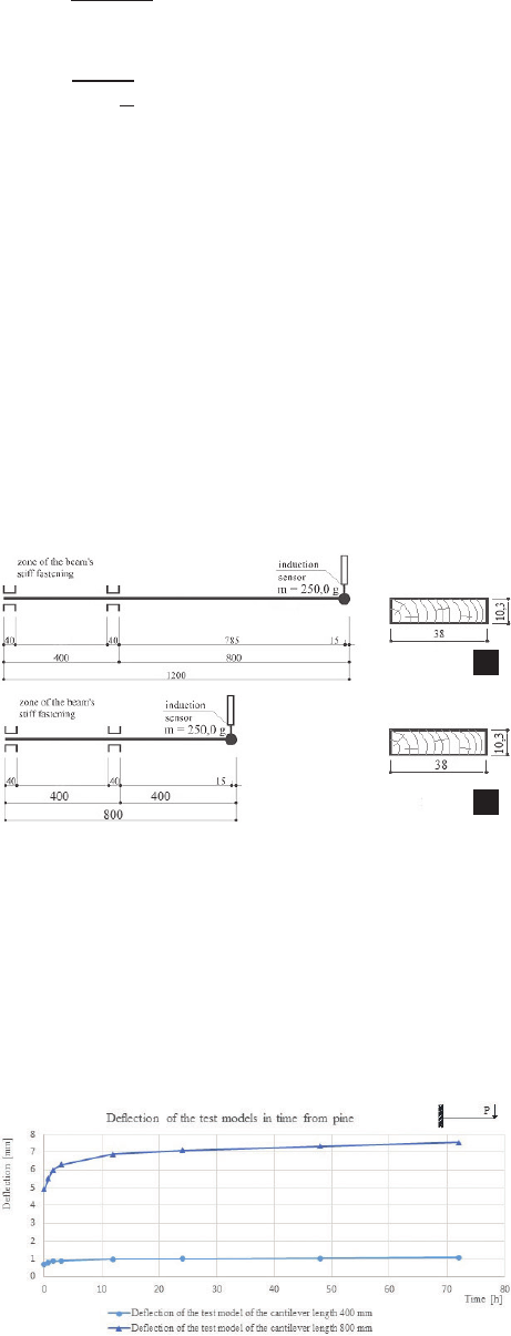
Fig. 4. Time-dependent deection of the free ends
of pine wood cantilevers (Fig. 3) during a 72-hour test
(elaborated by B. Misztal)
Il. 4. Zmiana w czasie ugięć swobodnych końców wsporników
z drewna sosnowego (Il. 3) w czasie próby trwającej 72 godzin
(oprac. B. Misztal)
Fig. 3. Model of the tested beam with cantilever length:
a) l
1
= 800 mm, b) l
2
= 400 mm
(schematic for dynamic testing and cross-section)
(elaborated by B. Misztal)
Il. 3. Model testowanej belki o długości wspornika:
a) l
1
= 800 mm, b) l
2
= 400 mm
(schemat belki do badań dynamicznych i przekrój)
(oprac. B. Misztal)
=
6
1
− 2
2
=
2
−
a
b
On the variability in time of the longitudinal modulus of elasticity E and the traverse modulus of elasticity G 119
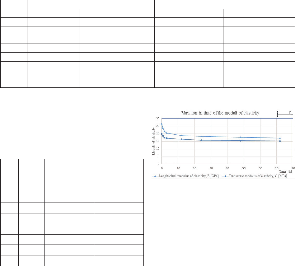
Fig. 5. Time-dependent changes in the modulus of longitudinal
elasticity E and modulus of transverse rigidity G
of pine wood cantilevers (Fig. 3)
during a 72-hour test
(elaborated by B. Misztal)
Il. 5. Zmiana w czasie modułów sprężystości podłużnej E
i sztywności poprzecznej G
wsporników z drewna
sosnowego (il. 3)
w czasie próby trwającej 72 godzin
(oprac. B. Misztal)
Time
Model of the cantilever length 800 mm Model of the cantilever length 400 mm
time [h] deflection [mm] time [h] deflection [mm]
t
0
0.00 4.91 0 0.71
t
1
0.75 5.50 0.75 0.79
t
2
1.5 6.00 1.5 0.86
t
3
3 6.30 3 0.90
t
4
12 6.90 12 0.98
t
5
24 7.10 24 1.01
t
6
48 7.33 48 1.04
t
7
72 7.55 72 1.07
Table 1. Chart of deflections in function of the time measured during 72 hours of the experiment (elaborated by B. Misztal)
Tabela 1. Wartości ugięć w funkcji czasu zmierzonego w ciągu 72 godzin doświadczenia (oprac. B. Misztal)
Time
Time
[h]
Longitudinal
modulus of elasticity
E [GPa]
Transverse
modulus of elasticity
G [MPa]
t
0
0 26.49 19.91
t
1
0.75 23.59 18.69
t
2
1.5 21.60 17.42
t
3
3 20.55 17.03
t
4
12 18.79 16.31
t
5
24 18.20 15.64
t
6
48 17.61 15.48
t
7
72 17.09 15.18
Table 2. List of modules of longitudinal rigidity
and transverse rigidity G of tested beams
(elaborated by B. Misztal)
Tabela 2. Zestawienie modułów sztywności
podłużnej i sztywności poprzecznej G
badanych belek wspornikowych
(oprac. B. Misztal)
Summary
The knowledge of the magnitudes of the longitudinal
elasticity E and that of the transverse elasticity G as well
as that of their variations in time has the meaning for the
further development of wooden constructions, including
glued wood. It allows to assess the load-carrying capacity
of a construction and the deformation of architectonic forms
in time. In the experiment conducted, the deections of the
loaded cantilevers increased in time and no stabilization of
the deections after 72 hours of the experiment’s duration
was noticed. It was demonstrated in this paper that on the
basis of the measurements of deections it was possible to
assess the magnitudes of the moduli of longitudinal elastici-
ty E and that of transverse elasticity G, as well as that those
values decrease jointly with the rise in deections in time.
The cause for the non-linear increase in deections
in time is the decreasing rigid elasticity EJ and shape ri
-
gidity FG of a beam made of pine-wood (J – moment of
cross-sectional inertia, F – cross-section of the beam). The
fact of decreasing the rigidity of wooden elements in time
requires a further recognition, especially for large-spatial
facilities made of glued wood.
The EC5 Standard considers the variability of deec-
tions and the strength of wood in time through the coe-
cient k
mod
, depending on the class of usage and that of last
duration. However, both testing as well as the recognition
of the variability of moduli and their strength in time shall
be further deepened since they also depend on the features
of the wood being a natural brous composite. The issue
is important, especially in the case of introducing on the
market of articial composites using wood.
Translated by
Wojciech Mühleisen
120 Barbara Misztal
References
Iimura, Yutaka. “Performance Evaluation of the Konohana Dome built
with Fast-Growing Sugi.” In World Conference on Timber Engineer-
ing, Miyazaki, 2–5 June 2008, Engineered Wood Products Associa-
tion, 2008.
Kowal, Zbigniew. “Kompozytowe pręty ściskane zbrojone podłużnie
i spi ralnie.” In Problemy naukowo-badawcze budownictwa. XLII Kon-
ferencja Naukowa Komitetu Inżynierii Lądowej i Wodnej PAN i Ko mi-
tetu Nauki PZITB, Kraków-Krynica, 1996. Vol. 2. Politechnika Kra-
kowska, 1996.
Lachiewicz-Złotowska, Agata, and Roman Orłowicz. “Zachowanie się
stref przypodporowych dźwigarów łukowych i belkowych z drewna
kle jonego.” Czasopismo Techniczne. Budownictwo, no. 104 (2007):
99–106.
Matsumoto, Akihiro, Morita Hideki, Fujimoto Yoshiyasu, Shiiba Atsushi,
Iimura Yutaka. “Strength Performance of Glulam made of Obi-sugi
Laminae with low Young’s Modulus of Bending.” In 2007 IUFRO All
Division 5 Conference, Taipei, October 29–November 2, 2007, Tapei.
Miyazaki Prefectural Wood Utilization Research Center, 2007.
Misztal, Barbara. “O występowaniu i wpływie na trwałość konstrukcji
drew nianych, zmiennego w czasie modułu sztywności poprzecznej G.”
In Dziedzictwo architektoniczne. Ochrona i badania obiektów zabytko-
wych, edited by Ewa Łużyniecka. Ocyna Wydawnicza Politechniki
Wrocławskiej, 2020.
Misztal, Barbara. Wooden Domes. History and Modern Times. Springer,
2018. https://doi.org/10.1007/978-3-319-65741-7.
Streszczenie
O zmienności w czasie modułów sprężystości podłużnej E i poprzecznej G
oraz ich wpływie na sztywność konstrukcji z drewna
W artykule sformułowano problem braku analizy zmian sztywności w czasie wielkoprzestrzennych konstrukcji z drewna klejonego, opisując kopułę
Konohana Dome w Japonii. Na przykładzie badań belki z drewna sosnowego o schemacie statycznym wspornika wykazano, że pomiar ugięć pozwala
oszacować sztywność sprężystą i postaciową modelu badawczego. Udowodniono także, że wraz ze wzrostem ugięć w czasie zmniejszają się moduły
sprężystości podłużnej E i poprzecznej G. Ujawniono, że przyczyną nieliniowego przyrostu ugięć w czasie jest malejąca sztywność sprężysta i posta-
ciowa belki wspornikowej.
Słowa kluczowe: moduł sztywności podłużnej, moduł sztywności poprzecznej, siła krytyczna, sztywność konstrukcji