
Introduction
The great durability of original cupolas made of so lid
wood is the result of a careful selection of wood for their
construction. The cupola described in [1] desig ned by
G. Moller, with a 33.50 m long diameter, built in 1822–
1827 as the roof for St. Ludwig’s Church in Darm stadt
(Germany), is a good example of such a structure [2].
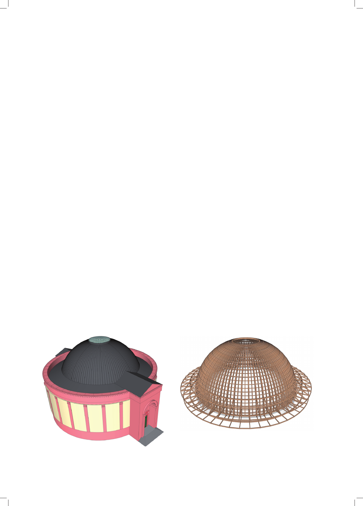
Figure 1 presents the view of St. Ludwig’s Church in
Darmstadt, and Figure 2 shows the structure of its cupola
made of oak wood ribs going horizontally and vertically.
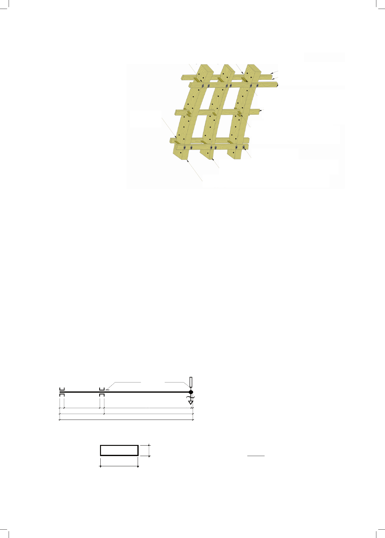
Figure 3 shows the system of the main vertical ribs bra-
ced with horizontal members
1
. The main vertical ribs
were made of five layers of centering with intermediate
ribs made of three layers of centering between them. The
vertical ribs were braced with double and single blocks
called chains. The cooperation between the vertical ribs
was provided by the bends of horizontal double ribs inser-
ted about 5.0 cm in the centering of vertical ribs. In order
to maintain the shape of the cupola the horizontal double
ribs were made of young, flexible oak wood. The single
horizontal ribs (called chains) with blocks were applied to
prevent the vertical ribs from buckling. These chains were
constructed from dry oak wood, chosen as a result of
years of carpentry experience, to provide for the technical
1
Figures 1–3 were made by the author on the basis of the cupola
construction diagram from the book Konstruktionen in holz by dr. Otto
Warth [2].
2014
1(37)
DOI: 10.5277/arc140108
Barbara Misztal*
Oszacowanie efektywnej sztywności i modułu sprężystości
różnych gatunków drewna na podstawie pomiarów drgań swobodnych
The calculation of effective stiffness and elasticity modulus of different
types of wood on the basis of measurements of free vibrations
Wprowadzenie
Zachowane do dzisiaj kopuły z drewna jednolitego
zawdzięczają swoją trwałość starannemu doborowi drew-
na na konstrukcję. Opisana w pracy [1] kopuła G. Molle-
ra, o średnicy 33,50 m, wybudowana w latach 1822–1827
jako przekrycie kościoła św. Ludwika w Darmstadt (Nie m
-
cy), jest przykładem takiego obiektu [2].
Na ilustracji 1 pokazano widok kościoła św. Ludwika
w Darmstadt, a na ilustracji 2 jego południkowo-rów no-
leżnikową konstrukcję kopuły żebrowej wykonanej z drew-
na
dębowego. Na ilustracji 3 przedstawiono usztyw nienie
głównych żeber południkowych stężeniami równo-
leżnikowymi
1
. Południkowe żebra główne wykonano
z pię ciu warstw krążyn. Pomiędzy żebrami głównymi
wbu dowano żebra pośrednie złożone z trzech warstw krą-
żyn. Stężenie żeber południkowych stanowiły pasy pod-
wójne i pojedyncze zwane łańcuchem. Aby zapewnić
współpracę żeber południkowych, wpuszczono pasy że -
ber równoleżnikowych, podwójnych w krążyny żeber
południkowych na głębokość około 5,0 cm. W celu do -
trzy mania kształtu konstrukcji kopuły podwójne żebra
równoleżnikowe wykonano z podatnego, młodego drew-
na dębowego. Pojedyncze żebra równoleżnikowe wraz
* Wydział Architektury Politechniki Wrocławskiej/Faculty of
Architecture, Wrocław University of Technology.
1
Ilustracje 1–3 wykonała autorka na podstawie schematu kon-
strukcji kopuły zawartego w książce dr. Otto Wartha Konstruktionen in
holz [2].
82 Barbara Misztal
efficiency of the construction and the durability of the
building until today.
So far, no better detailed methods of wood selection for
the construction of durable and prestigious engineering
structures have been developed than the visual ones
described in [3]. This paper offers to extend the traditio-
nal methods of the selection of material by using the
dynamic measurements disclosing the qualities of wood.
[4] and [5] show the use of measurements of parameters
of free vibrations in selecting wood elements with
a higher humidity from a group of similar elements. It
was demonstrated that the deviations in the frequency and
absorption of vibrations from expected values, especially
in complex structures with many similar elements, are an
important indicator of hidden defects of an element and
a system (Fig. 2).
Objective and description of tests
This paper describes the dynamic tests of free vibra-
tions of wood conducted on the following dry wood sam-
ples: pine, spruce, larch and oak. It shows how to use the
parameters of free vibrations determined in the tests, such
as stiffness and elasticity modulus, to calculate the quali-
ties of wood. It also demonstrates how to use the parame-
ters of free vibrations determined in the tests, such as
period of vibrations T, absorption of vibrations ρ, frequ-
ency ω, logarithmic absorption decrement
∆
, to calculate
the qualities of wood, especially effective stiffness K and
effective elasticity modulus E.
The calculation of K and E on the basis of the dynamic
tests is especially useful in the selection of wood in desi-
gning and evaluating the condition of structures as objec-
tive verification of universally applied visual inspections,
including the measurements of wood density and distance
between tree rings. The measurement of wood density
demonstrates the local quality of a member, whereas the
measurement of distance between tree rings depends on
subjective carpenter’s skills.
z przewiązkami (nazwane łańcuchami) stosowano w celu
zabezpieczenia żeber południkowych przed wybocze-
niem. Zbudowano je z suchego drewna dębowego. Tak
przemyślany dobór drewna na konstrukcję wynikający
z wie lowiekowych doświadczeń cieśli zapewnił do dzi-
siaj sprawność techniczną konstrukcji i trwałość obiektu.
Dotychczas nie opracowano dokładniejszych metod
wyboru drewna do budowy trwałych i prestiżowych kon-
strukcji inżynierskich niż te wizualne opisane w pracy [3].
W tym artykule autorka proponuje poszerzenie trady-
cyjnych metod doboru materiału w drodze wykorzystania
pomiarów dynamicznych ujawniających właściwości drew-
na. W pracy [4] i [5] pokazano wykorzystanie po mia rów
pa rametrów drgań swobodnych do wykrywania elementów
drewnianych o podwyższonej wilgotności w gru pie ele-
mentów podobnych. Pokazano, że ważnym wskaź nikiem
wad ukrytych elementu i systemu są od chyłki częstości i tłu-
mienia drgań od wartości oczekiwa nych, zwłaszcza w obiek-
tach złożonych o dużej liczbie ele mentów podobnych (il. 2).
Cel i opis badań
W niniejszym artykule opisano przeprowadzone bada-
nia dynamiczne drgań swobodnych drewna: sosny, świer-
ku, modrzewia i dębu w stanie powietrznosuchym. Poka-
zano, jak wykorzystać pozyskane z badań parametry
drgań swobodnych do obliczenia właściwości drewna,
takich jak sztywność i moduł sprężystości. Zobrazowano,
jak wykorzystać pozyskane z badań parametry drgań
swo bodnych: okres drgań T, tłumienie drgań ρ, częstość
ω, logarytmiczny dekrement tłumienia
∆
, do oszacowania
właściwości drewna, a zwłaszcza efektywnej sztywności
K i efektywnego modułu sprężystości E.
Oszacowanie K i E na podstawie badań dynamicznych
jest szczególnie przydatne do selekcji drewna, do pro je kto-
wa nia oraz do diagnostyki konstrukcji jako obiektywna
we ryfikacja stosowanych powszechnie oględzin, w tym po -
mia rów gęstości drewna i odległości pomiędzy słojami
dre wna. Pomiar gęstości drewna odzwierciedla lokal ną
Il. 1. Widok budynku kościoła św. Ludwika w Darmstadt
Fig. 1. View of St. Ludwig’s Church in Darmstadt
Il. 2. Konstrukcja kopuły drewnianej,
o średnicy 33,50 m,
kościoła św. Ludwika w Darmstadt
Fig. 2. Structure of the cupola made of wood, 33.50 m in diameter,
St. Ludwig’s Church in Darmstadt
Efektywna sztywność i moduł sprężystości drewna /Effective stiffness and elasticity modulus of wood 83
Tests of
wood models
The tests were conducted on models made of dry wood
beams, 10
×
40 mm in cross section and 1200 mm long.
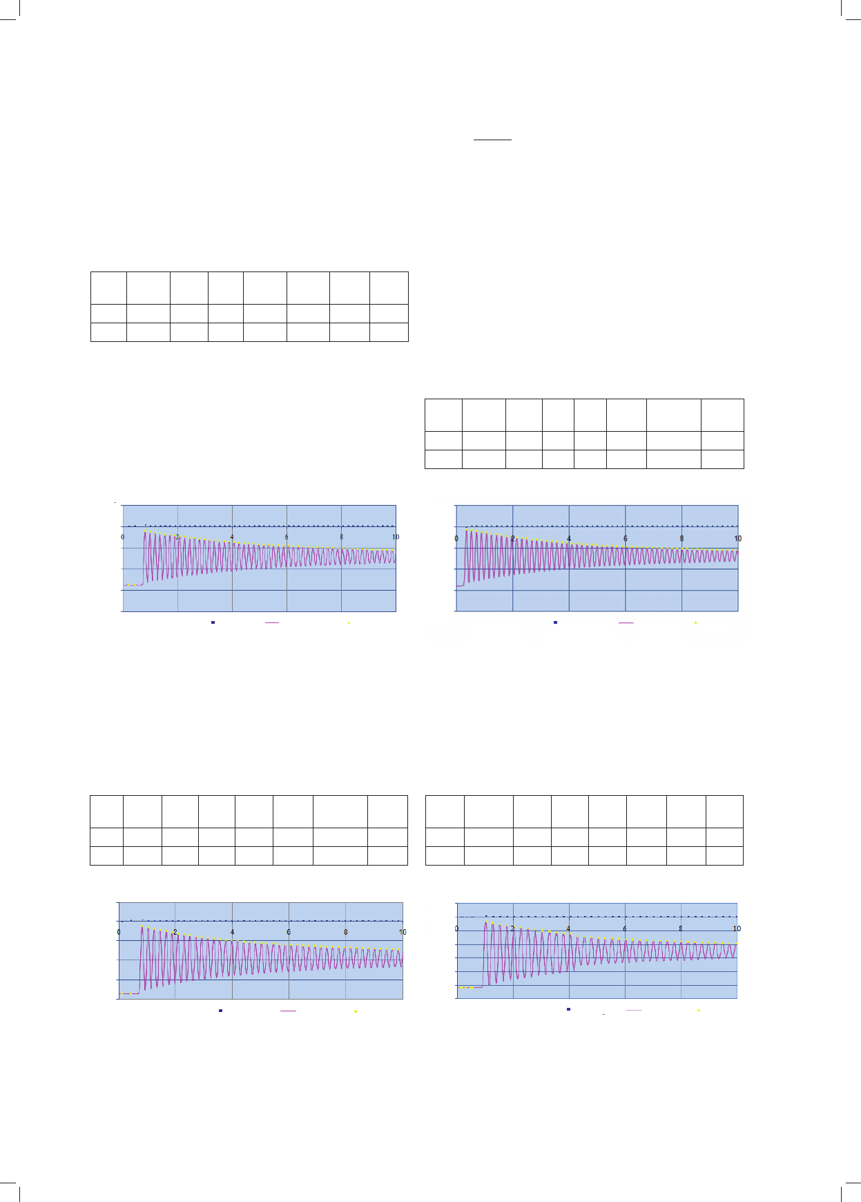
The vibrations were induced to the cantilever beams fixed
as shown in Figure 4.
The models made of dry boards were weighed before
the test. The load was applied at the end of the beam per-
pendicularly to the plane of lower stiffness of the beam.
A concentrated mass of m = 250.0 g was placed at the
end of the beam to limit the influence of secondary vi -
brations.
The test included the measurement of frequency n and
absorption ρ of free vibrations induced by impulse from
load P = 250.0 g suspended at the end of the beam. The
vibrations were induced by cutting the suspension of the
load. The parameters of the vibratory movement T, ρ, ω,
∆
(listed in Tab. 1–4) were calculated on the basis of
numerical results of the measurements with the use of
Excel spread sheets.
Table 1 shows the results of the tests of models made
of dry pine wood beams. The following tables and graphs
show the results of the tests of vibrations of models made
of dry spruce (Tab. 2, Fig. 6), larch (Tab. 3, Fig. 7), and
oak (Tab. 4, Fig. 8).
Analysis of dynamic
measurements
In all cases the absorbed free vibrations, regardless of
the variety of wood, were well described by the following
function (1) according to [6]:
y
t
= y
0
e
–ρt
cos(√α
2
– ρ
2
t + φ), (1)
where:
α – frequency of free vibrations,
ρ – dimensional absorption of vibrations,
φ – phase shift.
właściwość elementu, a pomiar odległości pomiędzy sło -
jami drewna zależy od subiektywnych umiejętnoś ci cieś li.
Badania modeli z drewna
Do badań przygotowano modele desek w stanie po wietrz-
nosuchym, o przekroju 10 × 40 mm, długości 1200 mm
.
W ruch drgający wprowadzano deski obciążone wsporni-
kowo jak na ilustracji 4.
Przed doświadczeniem modele z desek zważono w sta-
nie powietrznosuchym. Obciążenie wymuszające przy-
kładano na końcu wspornika prostopadle do płaszczyzny
mniejszej sztywności belki. W celu ograniczenia wpływu
drgań drugiego rzędu wprowadzono masę skupioną m =
250,0 g na końcu wspornika.
Badano częstość n i tłumienie ρ drgań swobodnych
wymuszonych impulsem za pośrednictwem obciążenia P =
250,0 g zawieszonego na końcu wspornika. Drgania wzbu-
dzano poprzez przecięcie zawiesia utrzymującego obciąże-
nie. Parametry ruchu drgającego T, ρ, ω,
∆
(zestawione
Il. 3. Połączenie żeber
południkowych zbudowanych
z kilku warstw krążyn z żebrami
równoleżnikowymi
Fig. 3. Vertical ribs made of
several layers of centering
braced with horizontal ribs
podcięcia krążyn zapobiegające nierównomiernemu osiadaniu żeber południkowych
insertions in the centering, preventing from uneven settlement of vertical ribs
podcięcia krążyn
insertions
in the centering
Żebro równoleżnikowe młode drewno
dębowe gr. 2,5 cm, szer. 10 cm
Hori zontal rib young oak wood
2.5 cm thick, 10 cm wide
przewiązki obustronne gr. 2,5 cm, szer. 5 cm,
śruba Ø10 / blocks on both sides 2.5 cm thick,
5 cm wide, bolt Ø10
przewiązki podwójne gr. 1,25, szer. 5 cm
Suche drewno dębowe / double blocks 1.25 cm
thick, 5 cm wide dry oak wood
Żebro równoleżnikowe „łańcuch”
gr. 1,25 cm, szer. 10 cm / Horizontal rib
“chain” 1.25 cm thick, 10 cm wide
śruby o średnicy 10 mm
bolts 10 mm in diameter
Żebro południkowe pośrednie – 3 krążyny gr. 5 cm, szer. 38 cm
Intermediate vertical rib – 3 centerings 5 cm thick, 38 cm wide
Żebro południkowe główne – 5 krążyn gr. 5 cm, szer. 38 cm
Main vertical rib – 5 centerings 5 cm thick, 38 cm wide
Il. 4. Model badawczy testowanych belek [3]
Fig. 4. Model of beams being tested [3]
a) Schemat belki do badań dynamicznych / Schematic diagram of
a beam for dynamic testing
b) przekrój
/ section
strefa sztywnego
zamocowania belki
area of rigid beam
fixing
40
10
10
40
40
785
785
15
P = 250,0 g
M = 250,0 g
400
800
1200
tensometr
elektrooporowy
czujnik
indukcyjny
inductive sensor
electroresistant
extensometer
320
40
84 Barbara Misztal
w tab. 1–4) wyznaczono na podstawie numerycznych wyni-
ków pomiarów za pomocą arkuszy kalkulacyjnych Excel.
W tabeli 1 przedstawiono wyniki badań modeli z desek
sosnowych w stanie powietrznosuchym. W kolejnych
The circular speed of absorbed vibrations:
ω = √α
2
– ρ
2
(2)
The circular speed of absorbed vibrations ω [˚] and
absorption ρ [1/s] were used to calculate the actual
effective K
ef
stiffness and the effective elasticity modulus
E
ef
of tested beams. Table 5 shows the results.
Publication [6] presents the relationship between stiff-
ness K, mass m, speed of vibrations ω, and absorption ρ.
If viscosity η is ignored, the local effective stiffness K
ef
of
the rod can be calculated with the following formula:
K
ef
= m
z
α
2
(3)
T
s
t
0
y
0
ρ
s
n
s
=
1/T
ω
s
φ∆
s
[s] [s] [mm] [1/s] [1/s] [°] [°]
0,186 0,5733 13,68 0,14 5,38 33,80 11,15 0,026
Tab. 1. Parametry drgań swobodnych modelu z sosny (il. 4)
Tab. 1. Parameters of free vibrations of the model
made of pine wood (Fig. 4)
Legenda do tab. 1–4 / Legend to Tab. 1–4:
T
s
– okres drgań / period of vibrations, t
0
– czas początkowy / initial time,
y
0
– maksymalne wychylenie / maximum inclination, ρ
s
– tłumienie
drgań / absorption of vibrations, n
s
– częstość drgań modelu / frequency
of vibrations of the model, ω
s
prędkość kołowa drgań tłumionych /
circular speed of absorbed vibrations,
φ
– przesunięcie fazowe / phase
shift,
∆
s
– lo ga rytmiczny dekrement tłumienia / logarithmic absorption
decrement, indeks s oznacza stan powietrznosuchy / index s means
dry wood
T
s
t
0
y
0
ρ
s
n
s
=
1/T
ω
s
φ∆
s
[s] [s] [mm] [1/s] [1/s] [1/s] [°]
0,173 0,2667 13,99 0,17 5,78 36,32 –3,49754 0,029
T
s
t
0
y
0
ρ
s
n
s
=
1/T
ω
s
φ∆
s
[s] [s] [mm] [1/s] [1/s] [1/s] [°]
0,21 0,72 18,76 0,148 4,762 30,0 21,70679 0,031
T
s
t
0
y
0
ρ
s
n
s
=
1/T
ω
s
φ∆
s
[s] [s] [mm] [1/s] [1/s] [1/s] [°]
0,253 0,11067 25,77 0,167 3,953 24,83 2,251 0,042
Tab. 2. Parametry drgań swobodnych modelu ze świerku (il. 4)
Tab. 2. Parameters of free vibrations of the model
made of spruce wood (Fig. 4)
Il. 5. Drgania swobodne modelu z sosny
w czasie pierwszych 10 s badań
Fig. 5. Free vibrations of the model made of pine wood
during the first 10 s of the test
Il. 6. Drgania swobodne modelu ze świerku
w czasie pierwszych 10 s badań
Fig. 6. Free vibrations of the model made of spruce wood
during the first 10 s of the test
Tab. 3. Parametry drgań swobodnych modelu z modrzewia (il. 4)
Tab. 3. Parameters of free vibrations of the model
made of larch wood (Fig. 4)
Il. 7. Drgania swobodne modelu z modrzewia
w czasie pierwszych 10 s badań
Fig. 7. Free vibrations of the model made of larch wood
during the first 10 s of the test
Il. 8. Drgania swobodne modelu z dębu
w czasie pierwszych 10 s badań
Fig. 8. Free vibrations of the model made of oak wood
during the first 10 s of the test
Tab. 4. Parametry drgań swobodnych modelu z dębu (il. 4)
Tab. 4. Parameters of free vibrations of the model
made of oak wood (Fig. 4)
wychylenie [mm] / inclination
wychylenie [mm] / inclination
wychylenie [mm] / inclination
wychylenie [mm] / inclination
5
5
0
0
-5
-5
-10
-10
-
-
15
15
-20
-20
5
5
0
0
-5
-5
-10
-10
-15
-15
-20
-20
5
5
0
0
-5
-5
-10
-10
-15
-15
-20
-20
5
5
0
0
-5
-5
-10
-10
-15
-15
-20
-20
-25
-25
-30
-30
czas [s]
czas [s]
time
time
czas [s]
czas [s]
time
time
czas [s]
czas [s]
time
time
czas [s]
czas [s]
time
time
okres
okres
period
period
okres drgań
okres drgań
okres drgań
okres drgań
okres drgań
okres drgań
period of vibrations
period of vibrations
period of vibrations
period of vibrations
period of vibrations
period of vibrations
wychylenie
wychylenie
inclination
inclination
wychylenie
wychylenie
inclination
inclination
wychylenie
wychylenie
inclination
inclination
wychylenie
wychylenie
inclination
inclination
maxima
maxima
maxima
maxima
maxima
maxima
maxima
maxima

Efektywna sztywność i moduł sprężystości drewna /Effective stiffness and elasticity modulus of wood 85
The equivalent concentrated mass m
z
was calculated
from formula (4) according to [7]:
m
z
= 0.243ql + 250, (4)
where: q – measured weight per 1 linear meter of beam.
The comparison of movements y = Pl
3
/3E
ef
J and y =
P/K
ef
resulted in the following equation (5):
(5)
The longitudinal elasticity modulus E
ef
was calculated
from the following equation (6):
(6)
The models made of wood were also subjected to exci-
tation with impulse six times as shown in Figure 4. After
the test was complete, which lasted for a dozen or so
minutes for each model excited to vibrate six times, the
deflections of the end of the beam were measured. The
deflection was called residual. Table 6 shows the residual
deflections of the tested models.
After some time the deflections decreased to the valu-
es which did not change any further. These deflections
were called permanent. Over a few dozen minutes the
tested models demonstrated the same residual and perma-
nent deflections as after long-term static tests.
After six series of impulse induced vibrations, softwo-
ods demonstrated the smallest residual deflection. Among
different varieties of softwood, larch demonstrates the
biggest permanent deflections. From among tested mo -
dels, spruce has the smallest and oak has the biggest resi-
dual and permanent deflections.
Conclusions
On the basis of dynamic tests one can therefore calcu-
late properties of wood elements such as stiffness and lon-
gitudinal elasticity modulus.
The results of the test described above provide for
a better understanding of the structural design of the
cupola by G. Moller from 1827 made of oak wood. Low
elasticity modulus of oak wood justifies the application of
horizontal bracing in the form of a so called “chain” made
of dry oak wood (Fig. 3). The “chains” reduce the length
of the buckling of vertical ribs along the plane of their
lower stiffness. The application of that solution, when
combined with a relatively low elasticity modulus E of
oak wood, can significantly increase the critical load
bearing capacity of the compressed vertical rib. The large
permanent deflections of this type of wood, confirmed in
dynamic tests, explain the application of double horizon-
tal ribs (Fig. 3) made of young oak wood. The double
horizontal bend adjusts to the displacements of vertical
ribs, maintaining, after a slight deformation, the shape of
the cupola.
The measurements of free vibrations of the models
made of wood are worth recommending when selecting
wood to be used in construction as well as when evalu-
ating the condition of historic buildings. The elements
tabelach i na wykresach zawarto wyniki badania drgań
modeli z desek: świerkowej (tab. 2, il. 6), modrzewiowej
(tab. 3, il. 7) i dębowej (tab. 4, il. 8), również badanych
w stanie powietrznosuchym.
Analiza pomiarów dynamicznych
We wszystkich przypadkach tłumione drgania swo-
bodne, niezależnie od gatunku drewna, dobrze opisywała
funkcja (1) według [6]:
y
t
= y
0
e
–ρt
cos(√α
2
– ρ
2
t + φ), (1)
gdzie:
α – częstość drgań własnych,
ρ – wymiarowe tłumienie drgań,
φ – przesunięcie fazowe.
Prędkość kołowa drgań tłumionych:
ω = √α
2
– ρ
2
(2)
Prędkość kołową drgań swobodnych ω [˚] i tłumienie
ρ [1/s], wykorzystano do oszacowania efektywnej K
ef
sztywności rzeczywistej i efektywnego modułu sprę żys-
tości E
ef
badanych belek. Wyniki zestawiono w tabeli 5.
W pracy [6] podano związki między sztywnością K,
masą m, prędkością drgań ω, i tłumieniem ρ. Pomijając
lepkość η można oszacować lokalną efektywną sztywność
K
ef
pręta ze wzoru:
K
ef
= m
z
α
2
(3)
Zastępczą masę skupioną m
z
oszacowano z wzoru (4) we -
dług [7]:
m
z
= 0,243ql + 250, (4)
gdzie: q – pomierzony ciężar na 1 mb wspornika.
Z porównania przemieszczeń y = Pl
3
/3E
ef
J i y = P/K
ef
otrzymano równanie (5):
(5)
Moduł sprężystości podłużnej E
ef
otrzymano z równa-
nia (6):
(6)
Modele z drewna poddano również sześciokrotnemu
wzbudzeniu impulsowemu według schematu pokazanego
na ilustracji 4. Po zakończeniu próby trwającej kilkana-
ście minut dla każdego modelu sześć razy wzbudzonego
do drgań pomierzono ugięcia końca wspornika. Ugięcie
po zakończeniu próby nazwano resztkowym. W tabeli 6
zamieszczono ugięcia resztkowe badanych modeli.
Ugięcia po pewnym czasie zmniejszały się do warto-
ści, która nie ulegała już zmianom. Ugięcia te nazwano
trwałymi. Modele badane w czasie kilkudziesięciu minut
wykazały takie ugięcia resztkowe i trwałe, jak po długo-
trwałych badaniach statycznych.
Najmniejsze ugięcie resztkowe po sześciu cyklach im -
pulsowo wzbudzonych drgań wykazują gatunki drzew
iglastych. Wśród gatunków iglastych największe ugię -
cia trwałe wykazuje modrzew. Wśród badanych modeli
Pl
3
P
=
3EJ K
ef
Pl
3
P
=
3EJ K
ef
K
ef
l
3
=
3J
E
ef
K
ef
l
3
=
3J
E
ef

86 Barbara Misztal
najmniejsze ugięcie resztkowe i trwałe ma świerk, naj-
większe dąb.
Wnioski
Na podstawie testów dynamicznych można oszacować
wartości własne elementów z drewna, takie jak sztywność
i moduł sprężystości podłużnej.
Wyniki badań uzyskane w opisanym eksperymencie
pozwalają lepiej zrozumieć rozwiązanie konstrukcji
z drew na dębowego – kopuły G. Mollera z 1827 r. Niski
mo duł sprężystości drewna dębowego uzasadnia zastoso-
wa nie równoleżnikowego stężenia usztywniającego w pos-
taci zwanej „łańcuchem” z suchego drewna dę bowego
(il. 3). „Łańcuchy” zmniejszają długość wy bo czeniową że -
ber południkowych w płaszczyźnie ich mniejszej sztyw-
ności. Zabieg ten pozwala przy stosunkowo małym mo -
dule sprężystości E drewna dębowego istotnie zwiększyć
nośność krytyczną ściskanego żebra południkowego. Po -
twierdzone w badaniach dynamicznych duże ugięcia trwałe
tego gatunku drewna uza sad niają
wbudowanie podwójnych
żeber równo leżnikowych (il. 3) z młodego drewna dębo-
we go. Podwójny pas rów no leżnikowy dopasowuje się do
przemieszczeń żeber południkowych, zachowując po nie-
wielkim odkształceniu kształt sfery kopuły.
Pomiary drgań swobodnych modeli z drewna warto po -
lecić do selekcji drewna stosowanego do budowy kon-
strukcji drewnianych, a także do diagnostyki obiektów za -
byt kowych. Elementy wzbudzone do drgań swobodnych,
pokazujące większe tłumienie, są w słabszym stanie tech-
induced to vibrate free, demonstrating a greater absorp-
tion, are in poorer technical condition than other boards in
the group of similar boards. The elements with higher fre-
quency of vibrations, lower absorption and lower logari-
thmic absorption decrement are in good technical condi-
tion and guarantee a greater durability of buildings.
Parametry dynamiczne modeli w stanie powietrznosuchym
badanych według il. 4
Dynamic parameters of dry models tested according to Fig. 4
m
z
K
ef
=
m
z
α
s
2
E
ef
modeli w stanie
powietrzno-
suchym
E
ef
of dry models
E
wg normy
E
per standard
materiał
material
masa
modelu
weight
of model
masa rów.
rozłożona
weight
uniformly
placed
ρ
s
ω
s
drgania
własne
free vibrations
ρ
s
2
ω
s
2
α
s
2
= ρ
s
2
+ ω
s
2
[g] [g/s
2
] [GPa] [GPa]
[g] [g/m] [1/s] [1/s] [1/s
2
]
12345 6 78 9 10
Sosna
Pine wood
260,70 178,15
0,14 33,80
285,498 326170,1 17,98
11÷14
0,0196 1142,44 1142,46
Świerk
Spruce wood
224,58 153,46
0,1724 36,3168
280,578 370065,5 20,40
0,0297 1318,91 1318,94
Modrzew
Larch wood
267,60 182,86
0,1485 30,01375
286,437 258035,6 14,23
0,0220 900,825 900,847
Dąb
Oak wood
314,42 214,85
0,1673 24,835
292,811 180607,3 9,96
brak danych
w normie
no data
within norm
0,028 616,777 616,805
Tab. 5. Porównawcze zestawienie efektywnej sztywności K
ef
i efektywnych modułów sprężystości E
ef
modeli badanych w stanie po wietrzno suchym
Tab. 5. The comparison of effective stiffness K
ef
and effective elasticity moduli E
ef
of dry tested models
Tab. 6. Zestawienie ugięć czterech gatunków drewna
po sześciu cyklach wzbudzenia do drgań masą 250,0 g
Tab. 6. List of deflections of four types of wood
after six series of induced vibrations with weight of 250.0 g
Gatunek drewna
Wood type
Ugięcie resztkowe
końca wspornika
po 6 wzbudzeniach
masą 250 g w mm
Residual deflection
of the end of the beam
after 6 excitations
with 250 g in mm
Ugięcie trwałe
w mm
końca wspornika
długości 785 mm
Permanent deflection
of the end of the
785 mm long beam
in mm
Sosna
Pine wood
0,29 0,05
Świerk
Spruce wood
0,13 0,02
Modrzew
Larch wood
0,39 0,07
Dąb
Oak wood
2,93 2,01

Efektywna sztywność i moduł sprężystości drewna /Effective stiffness and elasticity modulus of wood 87
Dynamic tests provide a quick comparative qualitative
assessment of the physical properties of wood. They
allow for evaluating the usability of wood in construction
after a few minutes and not a few days or even years as in
the case of long-term tests.
The measured effective elasticity moduli were greater
than in [8] which indicates the need to experimentally cal-
culate the stiffness of used materials.
Translated by
Tadeusz Szałamacha
nicznym niż inne deski w grupie desek podobnych. Ele men-
ty posiadające wyższe częstości drgań, mniej sze tłu mie nie
i mniejszy logarytmiczny dekrement tłu mienia są w do -
brym
stanie technicznym i zapewniają więk szą trwa łość
budowli.
Badania dynamiczne pozwalają na szybką po rów-
nawczą ocenę jakościową właściwości fizycznych drew -
na. Pozwalają na oszacowanie przydatności drewna do
wy korzystania w konstrukcji po kilku minutach, nie po
kil ku dniach, a nawet latach, jak w przypadku badań dłu-
go trwałych.
Pomierzone efektywne moduły sprężystości były
więk sze aniżeli w [8]. Wskazuje to na potrzebę do świad-
czalnego szacowania sztywności użytych materiałów.
Bibliografia /References
[1] Misztal B., Domes in architecture, „Architectus” 2010, nr 2(28),
289–293.
[2] Warth O., Konstruktionen in holz, J.M. Gebhardt’s, Leipzig 1900.
[3] Misztal B., Dynamic parameters of the free vibrations of various
wood species, „Architectus” 2012, nr 1(31), 125–128.
[4] Misztal B., Comparison of the Vibration Frequency and Damping
of Beam Models Made of Dry and Wet Pine Wood, WCTE 2008 –
10
th
World Conference on Timber Engineering – Miyazaki, JAPAN
– June 2–5, 2008.
[5] Misztal B., Kształtowanie kopuł z drewna jednolitego (Shaping
Domes of solid Wood), Oficyna Wydawnicza PWr, Wrocław 2012.
[6] Kowal Z., Dynamika nieważkiej belki na podporach lepkosprę-
żystych, „Archiwum Inżynierii Lądowej” 1966, 1(12), 29–42.
[7] Banasiak M. (red.), Ćwiczenia laboratoryjne z wytrzymałości
materiałów, PWN, Warszawa 1985.
[8] PN-B-03150. Konstrukcje drewniane. Obliczenia statyczne i pro-
jektowanie. PKN, Warszawa 2000.
Streszczenie
W artykule opisano badania dynamiczne modeli z drewna sosnowego, świerkowego, modrzewiowego i dębowego. Badania przeprowadzono w celu
osza cowania efektywnych sztywności K
ef
i E
ef
modułu sprężystości podłużnej różnych gatunków drewna. Przebieg drgań swobodnych każdego
z mo deli zilustrowano na wykresach. Pokazano różnice efektywnych modułów sprężystości drewna gatunków iglastych i liściastych. Oszacowane
mo duły sprężystości podłużnej E
ef
porównano z wartościami ujętymi w PN-B-03150:2000 Konstrukcje drewniane. Pokazano korzyści wynikające
z krótkich testów dynamicznych do wyznaczania i porównywania właściwości drewna. Otrzymane w wyniku analizy drgań swobodnych obiektyw-
ne dane o właściwościach drewna można wprowadzić na bieżąco do projektowania i diagnostyki konstrukcji, uściślając wizualne umiejętności cieśli.
Słowa kluczowe: dynamika, częstość drgań, tłumienie, logarytmiczny dekrement tłumienia, efektywna sztywność, efektywny moduł sprężystości
Abstract
The paper presents dynamic tests of models made of pine wood, larch, and oak. The tests were conducted in order to calculate the effective stiffness
K
ef
and E
ef
of the longitudinal elasticity modulus of different types of wood. The course of free vibrations of each of the models was illustrated in
graphs and the differences in effective elasticity modules of softwoods and hardwoods were presented. The calculated longitudinal elasticity modu-
li E
ef
were compared with the values provided in the standard PN-B-03150:2000 Wood Constructions. The benefits of quick dynamic tests to deter-
mine and compare the qualities of wood were demonstrated. The objective results of the analysis of free vibrations regarding the qualities of wood
can be used on a regular basis in designing and evaluating structures, adding to the visual capabilities of the carpenter.
Key words: dynamics, frequency of vibrations, absorption, logarithmic absorption decrement, effective stiffness, effective elasticity module
Rys. Paulina Starmach
Drawn by Paulina Starmach