
2021
2(66)
DOI: 10.37190/arc210210
Michał Malewczyk*
The usage of the openBIM idea in architectural design
on the example of Blender and BlenderBIM add-on
Introduction
Nowadays, the concept of BIM (building information
modeling) is considered as a standard, which combines
information about the geometry of a building and its parts
and also data describing the geometry, e.g., how an object
is used or its physical features. The advantages of using
the BIM concept in design have been described in many
scientic publications [1], [2]. The BIM concept is com-
plemented by the openBIM idea dened by the building-
SMART organization [3], which constitutes a universal
approach to the digital design process, openness of infor-
mation ow between entities constituting its parts, as well
as the building management.
The direct method of implementing the openBIM pos-
tulates is the standard of data recording and exchange
– In dustry Foundation Classes (IFC). This standard is
a clearly dened scheme for recording information about
the building, infrastructure elements, etc., in the assump-
tion that it is to enable the exchange of data, regardless of
what program the participant of the design process uses
[3]. IFC, as an open, ISO certied (ISO 16739-1:2018)
standard provides a set of denitions (so-called classes)
for buildings and building elements. It also provides the
structure of classes notation for unlimited reading by var-
ious computer applications. However, the IFC is only
a standard that does not have to be fully implemented.
The basic problem with the use of the IFC standard results
from the fact that it is not treated as a native way of
recording data created by specic BIM applications.
Thus, the data exchange forces the conversion of the BIM
model to the .ifc format. Therefore, cooperation very
often causes data loss, errors in the geometry of the model
itself and other problems [4]. The IFC standard itself is
also constantly developed and there is no nal version,
which means that it may not support some geometric ele-
ments or objects available in programs such as Archicad
or Revit.
According to the idea of openBIM, designing in this
standard should be open and enable cooperation at the
highest possible level [5]. Therefore, it should be noted
that from the designer’s point of view, not only data
exchange is important, but also the ability to work togeth-
er on the BIM model. Due to the way BIM applications
are organized, the above demand cannot be met. The IFC
standard applies only to data exchange and reading, not
editing. BIM design programs themselves do not provide
the tools to work together on one model in dierent pro-
grams either. The oered solutions are limited to a simpli-
ed conversion without the .ifc format. The Graphisoft
Archicad Connection [6] add-on can serve as an example.
Another important aspect related to cooperation on
a project created in a digital standard, including the BIM
standard, is access to software and materials. One of the
biggest problems with the adoption of BIM design software
is the cost of the software itself and other related addition-
al costs [7]. The above problem very often leads to a situ-
ation where some co-designers work in BIM software, and
some still use software for editing two-dimensional draw-
ings. A possibility of solving the above problem situation
is the use of open-source software [8]. Reducing the cost
of purchasing software to zero would certainly expand the
group of designers working in the BIM workow.
Objectives
Undoubtedly, designing in the BIM standard and im -
plementing the postulates of the openBIM idea cannot
take place without a specic tool – BIM software. The
* ORCID: 0000-0001-9585-1497. Faculty of Architecture, Gdańsk
University of Technology, e-mail: michal.malewczyk@pg.edu.pl
100 Michał Malewczyk
architectural design in the BIM standard. However, it
should be noted that the BlenderBIM add-on is an open
project, constantly updated and is not a nished version.
Therefore, some functions may not work as intended, and
the software itself may be buggy.
Methods
In the conducted research, the author focused on the
capabilities of the Blender program and the BlenderBIM
add-on, compared to other BIM software, in the context
of the openBIM idea. The author’s analyses relate to the
following issues:
1) the way and scope of integration of the Blender
environment and the BlenderBIM plugin with the IFC
standard,
2) possibilities of cooperation on the project in the
BIM standard oered by the Blender program and the
BlenderBIM add-on in terms of editing projects saved in
the IFC standard,
3) adapting the software to the various needs of the
designer,
4) access to the software.
Blender version 2.92 for MacOS and BlenderBIM ver-
sion 0.0.201025 were analyzed. To the best of the author’s
knowledge, the Blender program with the BlenderBIM
add-on has not been the subject of any scientic publica-
tion, nor have these programs been analyzed in the con-
text of the openBIM idea.
Integration with the iFC standard
The key element for the analysis of Blender and the
BlenderBIM add-on in terms of the level of integration
with the IFC standard is the method of recording the
information layer of the model. As already mentioned,
Blender and BlenderBIM add-on, unlike other programs
(such as Archicad or Revit), do not use object-oriented
modeling tools. The role of the designer is to create geom-
etry using Blender tools and supplement it with an infor-
mation layer using the BlenderBIM add-on. This plugin
uses only the IFC standard to describe the geometry. The
classication of the modeled elements of the building
geometry is carried out in three stages [13]. First, the
object should be placed in the appropriate folder, thanks
to which it will be assigned to, e.g., a suitable building and
oor. The folder structure, compliant with the IFC stand-
ard, can be generated automatically by the BlenderBIM
add-on, however, it is possible to create and edit it manu-
ally. The next step is to give the object an appropriate IFC
class, thanks to which it will be correctly recognized, e.g.,
as a wall or a window (regardless of the shape of the
geometry itself). The IFC class should be assigned to an
object by selecting a denition from the context menu
presenting all available classes. The nal step is to dene
the object’s attributes, i.e., its specic features (such as
physical features or wall function). The set of attributes
depends on the assigned IFC class. Each of these three
stages is directly based on the denitions of the IFC
standard, thus treating the discussed standard as a way of
modern IT industry provides designers with many possi-
bilities to choose applications with very dierent charac-
teristics [9]. The aim of this article is to present the
Blender program and the BlenderBIM add-on in terms of
the openBIM postulates implementation, in particular the
postulates about the openness of the designing process
and extending the possibilities of cooperation between
co-designers.
Blender and BlenderBIM
Blender is a software developed by the Blender Foun-
dation and made available on an open-source basis (the
GNU GPL license) [10]. It is a very powerful tool that
enables direct and parametric 3D modeling, it also has
tools for digital sculpting. Thanks to the built-in Cycles
and Eevee rendering engines and the Grease Pencil func-
tion, it allows you to create static renderings as well as 2D
and 3D animations. An additional functionality of the
program is the editing of raster graphics and movies,
which extends the program’s usefulness to the post-pro-
duction stage [11]. There is also a very strong software
development community. Thanks to making the program
available on an open-source basis, many add-ons have
been created that enable, for example, lighting analyzes
(Ladybug) or libraries of fully parameterized architectural
elements (Archipack). Despite a very wide range of func-
tions, this program was rather associated with the CGI
(Computer Generated Images), VFX (Visual Eects) and
computer games industries. The literature review did not
reveal any publication devoted to the use of Blender in
architectural design.
In October 2019, the BlenderBIM add-on was released.
It is an open-source extension to Blender, created by vol-
unteers from the ifcOpenShell project [12]. This add-on
allows you to read and write design les in the open IFC
standard, which allows you to design using Blender in the
BIM standard and to cooperate with other designers oper-
ating in the BIM workow (regardless of the program
used). The BlenderBIM extension is completely inte grated
with Blender and adds extra functionality to its interface.
Designing in the BIM standard using Blender and the
BlenderBIM add-on looks dierent in comparison with
other BIM applications. Programs such as Archicad and
Revit represent an object-oriented approach to modeling.
The user has a specialized tool at his disposal, suitable for
modeling specic elements, such as walls, ceilings or
stairs. Blender does not have any such object-oriented
tools as it is rather a traditional 3D modeler. The designer,
using the Blender functions, has to create the geometry of
the given object, and only at the second stage, using the
BlenderBIM add-on, adds the information layer to the
geometry. Such a solution treats geometry and informa-
tion separately, and creating the connection between these
two elements is the role of the designer. This is a very
dierent approach than other programs, however it un -
doubtedly provides great control over the geometry itself
and the information assigned to it.
Therefore, in the author’s opinion, Blender and
Blender BIM can be considered as a full-edged tool for
The openBIM idea in architectural design 101
recording data not only at the stage of data exchange, but
also at the time of their creation [13]. Due to the above,
the IFC standard is treated by BlenderBIM as a native
way of recording information about the model. A very
similar approach is represented by FreeCAD which, like
Blender, is not a BIM software by default, but a standard
CAD modeler. However, a special overlay allows to de -
scribe objects in accordance with the IFC standard. The
im plementation of the IFC standard in the case of solu-
tions presented by Blender and FreeCAD is much simpler
than in the case of other BIM programs. Support for the
IFC standard, despite the short history of BlenderBIM, for
example compared to Autodesk Revit, is much wider
[14]. It does not require creating new tools in the program
or objects, but it comes down to introducing new IFC
classes. At the same time, it should be noted that the dis-
cussed software still requires the project to be converted to
the .ifc format, however, in this case it is only related to the
translation of data into and from the Blender language.
Therefore, the traditional problems related to the conver-
sion to the .ifc format [4] should not occur, although their
occurrence cannot be ruled out.
Possibilities of cooperation
Due to the dierences resulting from a dierent ap -
proach to 3D modeling (and from other peculiarities that
each software has), there is often a need to use several
applications. Unfortunately, the ow of a BIM model be -
tween programs in order to edit it is basically impossible.
BIM applications allow the import of .ifc les, however,
they consider them only as a reference. Blender and
BlenderBIM can solve this problem by treating a le saved
in the .ifc format not as a reference, but as data that can
be imported and edited. For verication, the author mod-
eled a simple, single-layer wall in Autodesk Revit, which
was then exported to an .ifc le and imported to Blender.
After importing the .ifc le, BlenderBIM added access to
the model information. The wall is classied as ifcWall,
which means that the object is a wall according to the IFC
standard. It also had the ifcGlobalId (individual object
identication number), ifcPredenedType (predened
wall type) and ifcMaterial (wall material) attributes.
However, the very geometry of a rectangular, imported
object symbolizing a wall has lost the possibility of para-
metric editing. Changes could only be made directly.
Accordingly, the problem can only be considered partially
resolved. However, it should be noted that this is due not
so much to the limitations of the Blender and the
BlenderBIM add-on, but to the limitations of the IFC
standard itself, as well as the solutions used by manufac-
turers of other BIM software. Objects modeled in BIM
applications become non-parametric already at the time
of conversion to the .ifc format, which is related to two
issues. Firstly, each program has its own source code,
which may additionally use a dierent programming lan-
guage. Thus, dierent applications dene the same objects
dierently, and the layer of classes and attributes of the
IFC standard is somehow overwritten with the object only
at the time of conversion. Secondly, most BIM applica-
tions save geometry as Nurbs, i.e., surfaces described by
mathematical functions. Such a record of spatial informa-
tion allows for a high level of parameterization of the
model and does not introduce any limitations in the event
of a possible re-edition [15]. However, the IFC standard
uses 3D mesh geometry, which is based on a set of points,
edges and planes. In the case of planar elements, the dif-
ference is purely conventional, but in the case of more
complex surfaces or solids not composed of planes, the
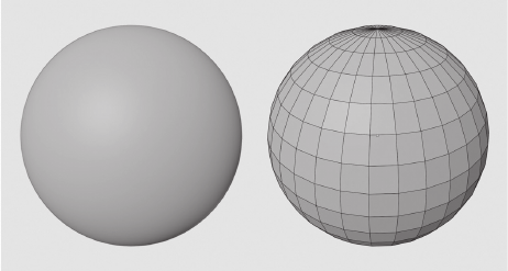
dierence is very clear. An example can be a sphere
which, written as Nurbs geometry, will be an ideal mathe-
matical sphere, and as a 3D mesh it will consist of trian-
gles or other planar polygons. A graphical comparison of
a sphere written as Nurbs and 3D mesh is shown in
Figure 1. The IFC standard uses 3D mesh geometry for
optimization reasons, and also because of the objectivity
of interpretation (independent of the computer program
used) of geometry recorded in the Cartesian coordinate
system. However, conversion of Nurbs geometry to 3D
mesh during the conversion of a BIM project to the IFC
standard causes many problems that make it dicult to
edit even using direct tools. If the edition is not a complex
interference, for example is limited to moving an opening
in the wall or changing its dimensions, the problem will
not be encountered. Clear complications appear when
edition means, for example, adding new holes in the wall
or removing previously modeled ones. In such a situation,
the surface should be detriangulated in the rst stage,
which consists in combining triangles with parallel direc-
tions of normal vectors into polygons (ngons). However,
there is a clear limitation in the case of 3D mesh geome-
try, which does not allow for full detriangulation of sur-
faces with cut openings, because 3D mesh geometry can
only consist of triangles (tris), quads and polygons
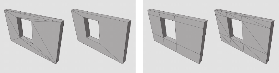
(ngons). Accordingly, a rectangular face with one rectan-
gular opening cut after conversion from Nurbs geometry
to 3D mesh and subjected to detriangulation will consist
of two polygons. Figure 2 shows the object before and
after detriangulation. The geometry transformed in this
way can be subjected to, for example, a Boolean opera-
tion, which will allow for cutting an additional hole in
a given place. However, the 3D mesh geometry consisting
Fig. 1. Graphical representation of a sphere
modeled as a B-Rep (left side) and a 3D mesh (right side)
(elaborated by M. Malewczyk)
Il. 1. Graficzna reprezentacja kuli zamodelowanej
jako B-Rep (lewa strona) oraz 3D mesh (prawa strona)
(oprac. M. Malewczyk)
102 Michał Malewczyk
only of quads is much easier to edit and also ts well with
the nature of most architectural objects. Composing 3D
mesh geometry from quadrilaterals also allows for rela-
tively safe data exchange between various 3D modeling
programs. Each quadrilateral can be divided into triangles
only in two dierent ways, in the case of polygons there
are many more possibilities. Such a method is therefore
denitely more geometrically unambiguous, and after
possible triangulation and detriangulation in another pro-
gram, the geometry is always saved in accordance with
the will of its creator. An example of a face composed of
quadrilaterals before and after triangulation is shown in
Figure 3. Apart from the editing diculties associated
with the conversion of Nurbs geometry to 3D mesh, there
are also frequent problems resulting from the conversion
itself, which fact has already been described in the litera-
ture [4]. Blender and BlenderBIM provide, therefore, the
possibility of cooperation on a BIM project created in
various programs, but for many reasons it is dicult. First
of all, it is not possible to use the parametric model edit-
ing capabilities oered by other programs, it also requires
modeling only using 3D mesh geometry. An additional
diculty limiting the possibilities of cooperation is the
need to work with .ifc les, which can be further edited
only in niche applications such as FreeCAD or usBIM.
viewer +.
Blender and BlenderBIM
in the context
of the diverse needs of designers
Undoubtedly, each architectural object is a complex
structure of individually designed elements, but also typi-
cal catalog objects. In addition, the design process itself
somehow forces the designers to approach each project
individually. Accordingly, the needs of designers for a BIM
design program are very diverse. These needs relate pri-
marily to the modeling methods. Blender oers several
possibilities in this regard.
The basic modeling method oered by Blender is
direct modeling. The user has a morphing method and
a curve method at his disposal. The morphing method
involves editing basic objects such as a cube, cylinder or
sphere, and this method is not available in programs such
as Archicad because it is characteristic of traditional 3D
modelers, not CAD programs. The functionality of Blender
can be compared in this respect to programs such as
3DSmax, Cinema4D or Maya. At the editing stage, the
user has access to several hundred tools that allow for
extruding, cutting geometry or sculpting with digital brush-
es. It is a great way to model small architectural forms
(e.g., benches, lamps) or details (e.g., drainage gullies, roof
hatches). The curves method is based on creating three-
-d
imensional geometry on the basis of curves moved
along other curves or combining a series of curves into
surfaces (the curves in this case are the sections of the
generated surface). This type of modeling allows you to
quickly create the geometry of balustrades or topographic
surfaces or coatings, and the functionality of the Blender
program is similar in this respect to both CAD and BIM
programs, as well as traditional 3D modelers.
Blender also has a lot of tools that allow you to param-
eterize elements created directly. In this scope, the user
has the option of imposing constraints on the model (for
example, connecting windows with the external wall, in
eect moving one triggers an action on the other) or cre-
ating parameters [16] (global or object-oriented, which
allows for editing, for example, the height of all stories of
the building or specic window width). It is also possible
to add parametric modiers (for example, dynamically
copying repetitive elements such as stairs and columns).
Since the user can also create their own scripts in this area
using the Python – open programming language, the pos-
sibilities of the program in this area are almost unlimited.
It should be noted, however, that creating all parameters
and assigning them to objects is done manually, which
requires a lot of experience with the software.
The application also provides solutions that enable
fully parametric design using graphical programming,
similar to, for example, the Grasshopper add-on imple-
mented in the Rhinoceros modeler or Dynamo built into
the Autodesk Revit program. One such solution is availa-
Fig. 2. Wall converted from a Nurbs to a 3D mesh (left side)
and after detriangulation (right side)
(elaborated by M. Malewczyk)
Il. 2. Ściana po konwersji Nurbs 3D mesh (lewa strona)
oraz po detriangulacji (prawa strona)
(oprac. M. Malewczyk)
Fig. 3. Wall modeled as a 3D mesh, composed of quads,
before (left side) and after triangulation
(elaborated by M. Malewczyk)
Il. 3. Ściana zamodelowana jako 3D mesh, składająca się z czworokątów,
przed triangulacją (lewa strona) oraz po triangulacji (prawa strona)
(oprac. M. Malewczyk)
The openBIM idea in architectural design 103
ciated with the tool. Naturally, the concept of making all
BIM design software open-source is utopian. Moreover, it
should be mentioned that the concepts of open and closed-
source complement and support each other, as Lerner and
Schankerman wrote about (after: [8]).
Conclusions
The idea of openBIM in its basic assumption is to allow
an unlimited ow of information between entities partici-
pating in the design process. The actual form of imple-
menting this idea is the IFC standard, which allows the
BIM model to be read by software from dierent manufac-
turers. However, there are many problems with the actual
use of this standard in practice. The necessity to convert
and the fragmented handling of IFC classes (dierent in
dierent programs) very often causes various types of
errors in the information about the model or in the geom-
etry itself. The current state of development of most BIM
modeling programs also does not allow for the joint edit-
ing of model geometry using dierent applications.
Despite the very advanced method of implementing
the openBIM idea (as evidenced by the award granted to
the team creating BlenderBIM in 2020 by the building-
SMART organization) and the editing capabilities of .ifc
les, Blender and BlenderBIM have many features that
make their use in everyday design dicult. These dicul-
ties are mainly due to the level of development of these
tools and the structure of the BIM modeling software
market. Undoubtedly, the implementation of some of the
solutions that Blender and BlenderBIM oer to the major-
ity of BIM programs would signicantly facilitate co -
operation on the project. The key element seems to be
a so lution treating the IFC standard as a native way of re -
cording information about the BIM model and covering
most
of this standard with support. The development of
support for 3D Mesh geometry also seems to be important
in the process of implementing the openBIM idea.
According to the example of the Blender program (in
which the geometry is initially saved as 3D mesh, not as
Nurbs), there is no need to convert the geometry, which
reduces the risk of errors when writing data and reading
them in other software, and also signicantly increases
the editing possibilities of the geometry in other 3D mod-
eling programs.
Despite the obvious benets of using computer tools in
design, there are also many limitations connected with
them. Modern programs in most cases constitute closed,
heterogeneous environments, which signicantly hinders
cooperation between participants in the design process.
Taking into account nancial factors and design needs
mostly results in a signicant reduction of the pool of
applications to choose from. Extending the idea of open-
BIM is an undoubted chance for designers to work better,
more eciently, but also for the architectural form itself,
potentially less limited by the program that was used to
design it.
Translated by
Michał Malewczyk
ble in Blender from version 2.92 (geometric nodes), and
there is also an add-on called Sverchok, which is open-
access. Despite the lack of publications comparing the
functionality of the solutions oered by Blender with
other available solutions, those oered by Blender are
much shorter developed. Therefore, it can be presumed
that their usefulness is lower.
Because thanks to the BlenderBIM add-on, Blender sup-
ports the .ifc format, the user also has the option of employ-
ing ready-made models available, for example, on the
manufacturers’ websites. The use of these types of objects
does not require additional work related to assigning classes
and attributes to the IFC standard, as these objects already
have such information. In addition, it is also possible to use
ready-made 3D models that are not, by denition, objects
to be used in designing in the BIM standard. However,
information about the IFC class and attributes should be
completed individually for such a model. An additional
advantage of the analyzed software in terms of the use of
ready-made libraries is the possibility of creating refer-
ences to external les, therefore there is no need to nest
models in the main le. This solution signicantly im -
proves the speed of work on the project and allows you to
reduce the size of les.
In addition to the design itself, an important element of
the designer’s work is the preparation of documentation.
The Blender program and the BlenderBIM add-on oer
very limited possibilities in this regard, which are only in
the initial stage of development. The user has only the
tools to export the cross-sections created with at view-
ports and very limited possibilities of drawing descrip-
tion. The analyzed programs do not have tools for creat-
ing lists or intelligent dimensioning tools present in other
leading BIM programs.
Therefore, Blender and BlenderBIM are software with
very dierent functionalities, giving access to many dier-
ent modeling methods not available in other BIM applica-
tions. Nevertheless, due to the initial phase of BlenderBIM
development and other types of Blender starting purpose,
they do not give access to other, highly specialized tools
implemented in other BIM applications. First of all, they
make it almost impossible to create full, professional pro-
ject documentation.
Open-source
A clear extension of the openBIM idea is the open-
source concept, according to which the Blender software
and the BlenderBIM add-on are made available, as well
as the IFC standard itself. In the same way, the previously
mentioned FreeCAD program is made available. Free
access to software in the context of the openBIM idea
allows you to use the discussed applications without any
restrictions in order to analyze ready-made projects writ-
ten in the openBIM standard, but also for the design itself.
In line with the third freedom, as dened by the denition
of free software [17], making a program available on an
open-source basis also enables more advanced participa-
tion of the developers themselves in the process of creat-
ing the tool. Thanks to this, the designer can be more asso-
104 Michał Malewczyk
References
[1] Foremny A., Wykorzystanie BIM w fazie wykonawczej przedsię-
wzięć budowlanych, “Materiały Budowlane” 2013, R. 12, nr 496,
82–85.
[2] Grzyl B., Migda W., Apollo M., Building Information Modeling in
Small and Middle Sized Buildings – Case Study, “IOP Conference
Series: Materials Science and Engineering” 2019, Vol. 603, Iss. 3,
1–10, doi: 10.1088/1757-899x/603/3/032077.
[3] Jiang S., Jiang L., Han Y. et al., OpenBIM: An Enabling Solution for
Information Interoperability, “Applied Sciences” 2019, 9(24), 5358,
doi: 10.3390/app9245358.
[4] Lai H., Deng X., Interoperability analysis of IFC-based data ex -
change between heterogenous BIM software, “Journal of Civil En -
gineering and Management” 2018, vol. 24, No. 7, 537–555, doi: 10.
3846/jcem.2018.6132.
[5] BuildingSMART International, What is openBIM? https://www.
buildingsmart.org/about/openbim/openbim-denition/ [accessed:
1.04.2021].
[6] GRAPHISOFT, Graphisoft Archicad Connection Add-in, 2017.
http://download.graphisoft.com/ftp/techsupport/downloads/
interoperability/GRAPHISOFT%20ArchiCAD%20Connection%20
for%20Revit%202015.pdf [accessed: 1.04.2021].
[7] Olatunji A.O., Modelling the costs of corporate implementation of
building information modelling, “Journal of Financial Management
of Property and Construction” 2011, Vol. 16, Iss. 3, 211–231, doi:
10.1108/13664381111179206.
[8] Siewczyński B., Architektura wobec idei Open Source, “Archivolta”
2014, nr 2(61), 17–20.
[9] Logothetis S., Stylianidis E., BIM Open Source Software (OSS) for
the documentation of cultural heritage, “Virtual Archaeology
Review” 2016, Vol. 7, No. 15, 28–35, doi: 10.4995/var.2016.5864.
[10] https://www.blender.org/about/ [accessed: 8.01.2021].
[11] https://www.blender.org/features/ [accessed: 8.01.2021].
[12] https://blenderbim.org [accessed: 8.01.2021].
[13]
https://blenderbim.org/blenderbim-tutorial.html [accessed: 7.02.2021].
[14]
https://blenderbim.org/blenderbim-vs-revit.html [accessed: 7.02.2021].
[15] Nurbs Modeling, Alias, Toronto 2004.
[16] Brito A., Blender parametric modeling: Drivers, Custom Pro per-
ties, and Shape Keys for 3D modeling, [independently published]
2019.
[17]
https://www.gnu.org/philosophy/free-sw.pl.html [accessed: 7.02.2021].
Abstract
The usage of the openBIM idea in architectural design on the example of Blender and BlenderBIM add-on
The aim of the article is an analysis of the method and advancement of the openBIM idea implementation, clearly dened by the buildingSMART
organization. The conducted analyses are limited to the Blender program and the BlenderBIM add-on and were embedded in the context of the work
of an architect and other IT solutions. The article presents four aspects of the openBIM concept implementation. The rst approach relates to a pro-
cess of data exchanging between dierent computer applications using the open IFC standard. Another two focus on the method of creating and
coding the three-dimensional geometry itself, through the prism of cooperation between various entities and further editing possibilities. The last
aspect deals with the extension of the openBIM concept by combining it with the open-source idea. The author bases his considerations on the
existing, analyzed scientic material, as well as on his own experience in the everyday reality of a designer and a teacher.
Key words: openBIM, Blender, BlenderBIM, IFC, buildingSMART
Streszczenie
Zastosowanie idei openBIM w projektowaniu architektonicznym na przykładzie programu Blender oraz dodatku BlenderBIM
Tematem niniejszego artykułu jest analiza sposobu oraz zaawansowania realizacji idei openBIM, jasno zdeniowanej przez organizację building-
SMART. Przeprowadzone badania ograniczają się do przykładu programu Blender oraz dodatku BlenderBIM i zostały osadzone w kontekście
pracy projektanta, architekta oraz innych rozwiązań informatycznych. W artykule zostały przybliżone cztery aspekty realizacji koncepcji openBIM.
Pierwsze ujęcie odnosi się do sposobu wymiany danych pomiędzy różnymi aplikacjami komputerowymi za pomocą otwartego standardu IFC. Drugi
oraz trzeci wymiar skupia się na sposobie tworzenia oraz zapisu samej geometrii trójwymiarowej, przez pryzmat współpracy różnych podmiotów
i dalszych możliwości edycyjnych. Ostatni aspekt dotyczy rozszerzenia idei openBIM poprzez jej połączenie z koncepcją open-source. Autor swoje
rozważania opiera na istniejącym, przeanalizowanym materiale naukowym, a także na własnych doświadczeniach w codzienności projektowej oraz
dydaktycznej.
Słowa kluczowe: openBIM, Blender, BlenderBIM, IFC, buildingSMART